Power tool having pneumatic vibration dampening

a technology of pneumatic dampening and power tools, which is applied in the field of power tools, can solve the problems of unfavorable counterweight reduction, unfavorable reducing of vibration in power tools, and undesired vibration toward the rear side or toward of power tools, so as to achieve the effect of alleviating vibration in power tools

Active Publication Date: 2007-04-17
MAKITA CORP
View PDF11 Cites 43 Cited by
  • Summary
  • Abstract
  • Description
  • Claims
  • Application Information

AI Technical Summary

Problems solved by technology

In the known electric hammer, the fluctuation of air pressure for driving the tool bit may cause vibration in the electric hammer.
As a result, undesired compression of air may occur and cause undesired vibration toward the rear side of the power tool or toward the user holding the power tool.
However, the counter weight may not always effectively reduce vibration caused by air fluctuations within the electric hammer.

Method used


Image

  • Power tool having pneumatic vibration dampening
  • Power tool having pneumatic vibration dampening
  • Power tool having pneumatic vibration dampening

Examples


first representative embodiment

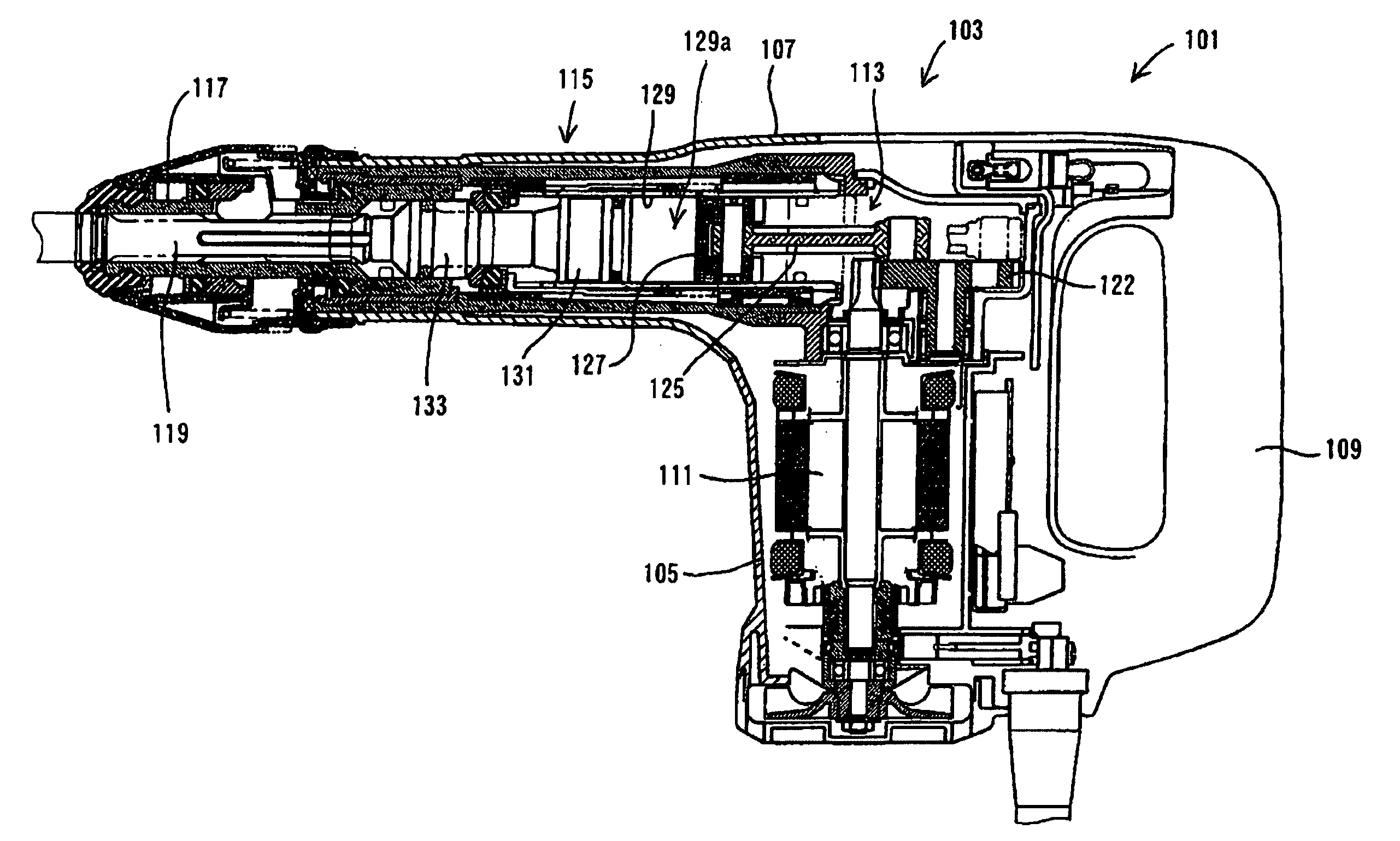
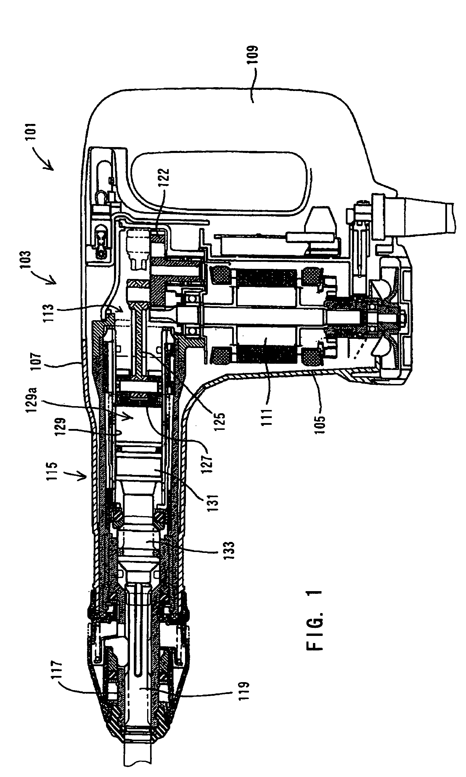
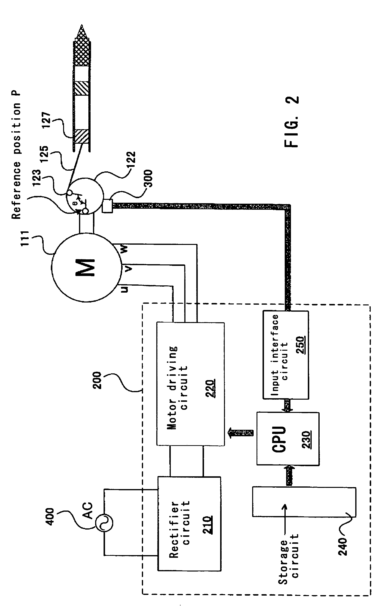
[0037]First representative embodiment of the present invention will now be described with reference to the drawings. FIGS. 1 and 2 show an electric hammer 101 as a representative embodiment of the power tool according to the present invention. FIG. 1 is a sectional view showing the entire electric hammer 101. FIG. 2 is a block diagram of the control system of the electric hammer 101 shown in FIG. 1.

[0038]As shown in FIG. 1, the representative electric hammer 101 includes a body 103, a tool holder 117 connected to the tip end region of the body 103, and a hammer bit 119 detachably coupled to the tool holder 117. The hammer bit 119 is a feature that corresponds to the “tool bit” according to the present invention.

[0039]The body 103 includes a motor housing 105 that houses a driving motor 111, a gear housing 107 that houses a driving force transmitting mechanism 113 and a striking mechanism 115, and a handgrip 109. The driving force transmitting mechanism 113 converts the rotating outp...

second representative embodiment

[0081]Second representative embodiment is now described in detail in reference to FIGS. 5 to 13. As to the feature of the second representative embodiment that is substantially identical to the feature of the first representative embodiment, same reference number is used and detailed explanation is abbreviated for the sake of convenience. In the electric hammer 201 according to the second representative embodiment, a vibration sensor 500 for detecting acceleration (detecting information about vibration) caused in the region of the handgrip 109 is disposed within the body 103. The acceleration caused in the region of the handgrip 109 is a feature that corresponds to the “vibration information” in the present invention.

[0082]Further, in the electric hammer 201, the vibration sensor 500 detects acceleration caused in the body 103 of the hammer 201, and the detected information is inputted to the CPU 230 via the input interface circuit 250 as shown in FIG. 6. The vibration sensor 500 an...


PUM

PropertyMeasurementUnit
crank position angleaaaaaaaaaa
carrier frequencyaaaaaaaaaa

Abstract

It is an object of the present invention to provide a vibration reducing technique caused by air pressure fluctuations within a power tool. According to the present invention, a representative power tool may comprise a driving motor, a driver and a tool bit. The driving motor drives the driver to cyclically reciprocate. The tool bit is linearly driven by utilizing the pressure of air within the power tool. The air may be compressed by the reciprocating movement of the driver. The power tool changes the rotational speed of the driving motor in the cycle of the reciprocating movement of the driver so that vibration caused in the power tool can be alleviated.

Description

CROSS REFERENCE[0001]This application claims priority to Japanese patent application number 2003-204411, filed Jul. 31, 2003 and Japanese patent application number 2004-160077, filed May 28, 2004, each of which are incorporated herein by reference as if fully set forth herein.BACKGROUND OF THE INVENTION[0002]1. Field of the Invention[0003]The present invention relates to a power tool such as an electric hammer and more particularly, to a technique of reducing and alleviating vibration in a power tool.[0004]2. Description of the Related Art[0005]A known power tool such as an electric hammer generally includes a driving motor, a driver driven by the driving motor to reciprocate and a tool bit. The known electric hammer linearly drives a driven-side member, such as a striker by utilizing the pressure fluctuation of air within the power tool. Such air is compressed by a reciprocating movement of the driver. When the driven-side member is linearly driven, the tool bit is also linearly dr...

Claims


Application Information

Patent Timeline
Patent Type & Authority Patents(United States)
IPC IPC(8): B25D9/00B25D11/12B25D17/24
CPCB25D11/125B25D17/24Y10T74/2131B25D2250/201B25D2250/221B25D2211/003
Inventor SAKAI, MITSUNORI
Owner MAKITA CORP
Why Eureka
Try Eureka