Electrical connector with a terminal retainer with an intermediate lock

a technology of intermediate lock and retainer, which is applied in the direction of electrical apparatus, connection, coupling device connection, etc., can solve the problem that the retainer is not at the normal depth of the retainer-mounting hol

Inactive Publication Date: 2007-04-17
SUMITOMO WIRING SYST LTD
View PDF7 Cites 24 Cited by
  • Summary
  • Abstract
  • Description
  • Claims
  • Application Information

AI Technical Summary

Benefits of technology

[0008]An overlap length of the locking surface for the to-be-locked surface of the housing preferably is larger at the intermediate lock than at the side locks. This way of adjusting the locking strength allows the connector to be manufactured more easily than adjusting the locking strength by differentiating a material for the intermediate lock and a material for the side locks from each other.
[0009]The intermediate lock preferably is at a central widthwise position of the retainer. Therefore the retainer is balanced well and the retainer-mounting work can be accomplished smoothly.
[0011]The terminal fittings are inserted into the respective cavities and the retainer then is mounted in the retainer-mounting hole. The side locks of the retainer lock the corresponding to-be-locked surfaces of the housing when the retainer is mounted in the retainer-mounting hole at the normal depth. At this time, the intermediate lock also locks the corresponding to-be-locked surface of the housing. As a result, the terminal fittings are held in the respective cavities. The retainer is long in the width direction. However, the intermediate lock and the side locks prevent the central portion of the retainer from warping. The locking strength of the intermediate lock exceeds the locking strength of the side locks. Therefore, neither the intermediate lock nor the side locks lock if the terminal fittings are left in a semi-inserted state at the central portion of the housing. Similarly, if the terminal fittings at one end of the housing are left in a semi-inserted state, the side lock at the side of the housing is not locked, and the retainer deforms up at its side. Therefore, the semi-inserted state of the terminal fitting can be confirmed visually.
[0012]The retainer preferably is mounted in the retainer-mounting hole at the predetermined normal depth when the terminal fittings are inserted into the respective cavities. Therefore, the leading end of the detector of the housing and the leading end of the detector of the retainer are flush with each other. The retainer is not mounted in the retainer-mounting hole at the predetermined normal depth when the terminal fittings are left in the semi-inserted state in the cavities. Thus, the leading end of the detector of the housing and the leading end of the detector of the retainer are not flush with each other. Therefore by visually checking the positions of the leading ends of both detectors, it is easy to detect that the terminal fittings have been semi-inserted into the cavities.

Problems solved by technology

However, the retainer is not at the normal depth in the retainer-mounting hole when the terminal fittings are left in a semi-inserted state in the cavities.

Method used


Image

  • Electrical connector with a terminal retainer with an intermediate lock
  • Electrical connector with a terminal retainer with an intermediate lock
  • Electrical connector with a terminal retainer with an intermediate lock

Examples


Embodiment Construction

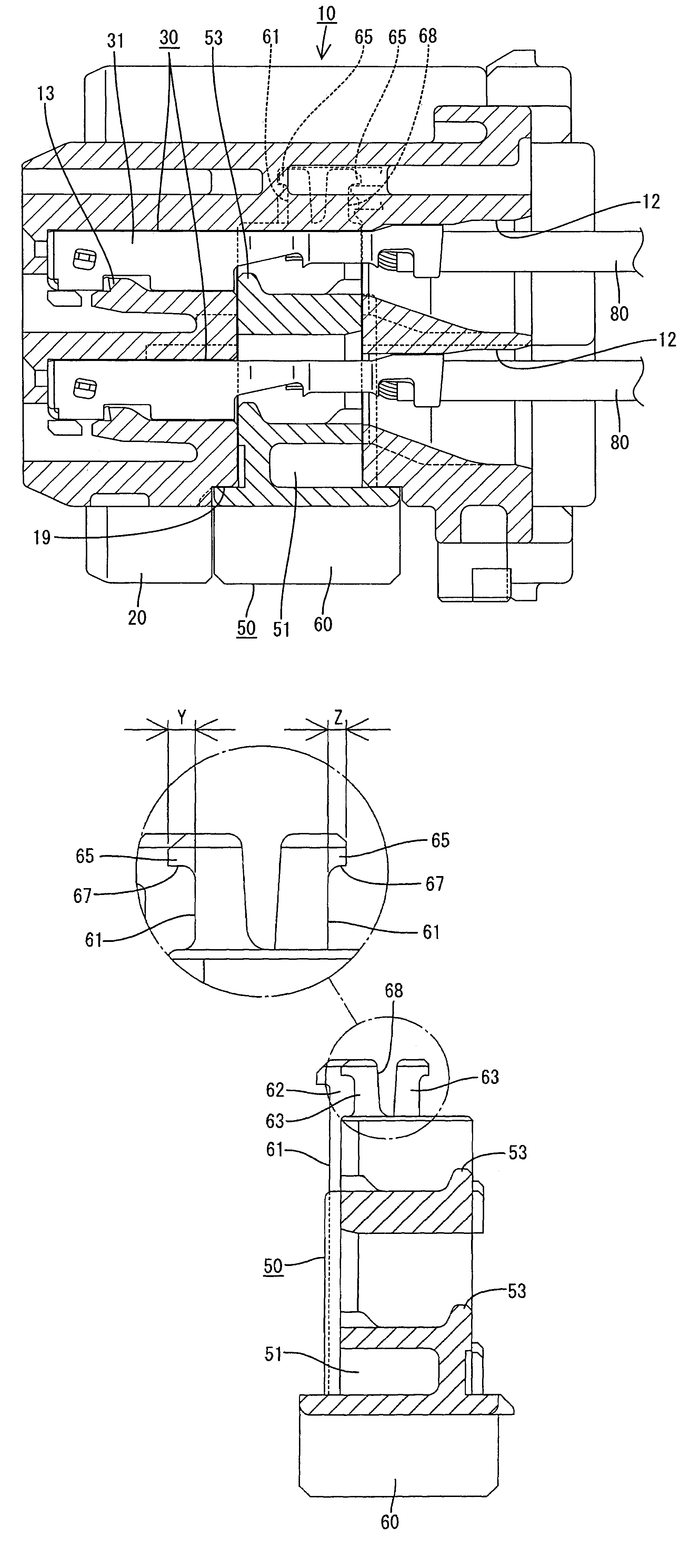
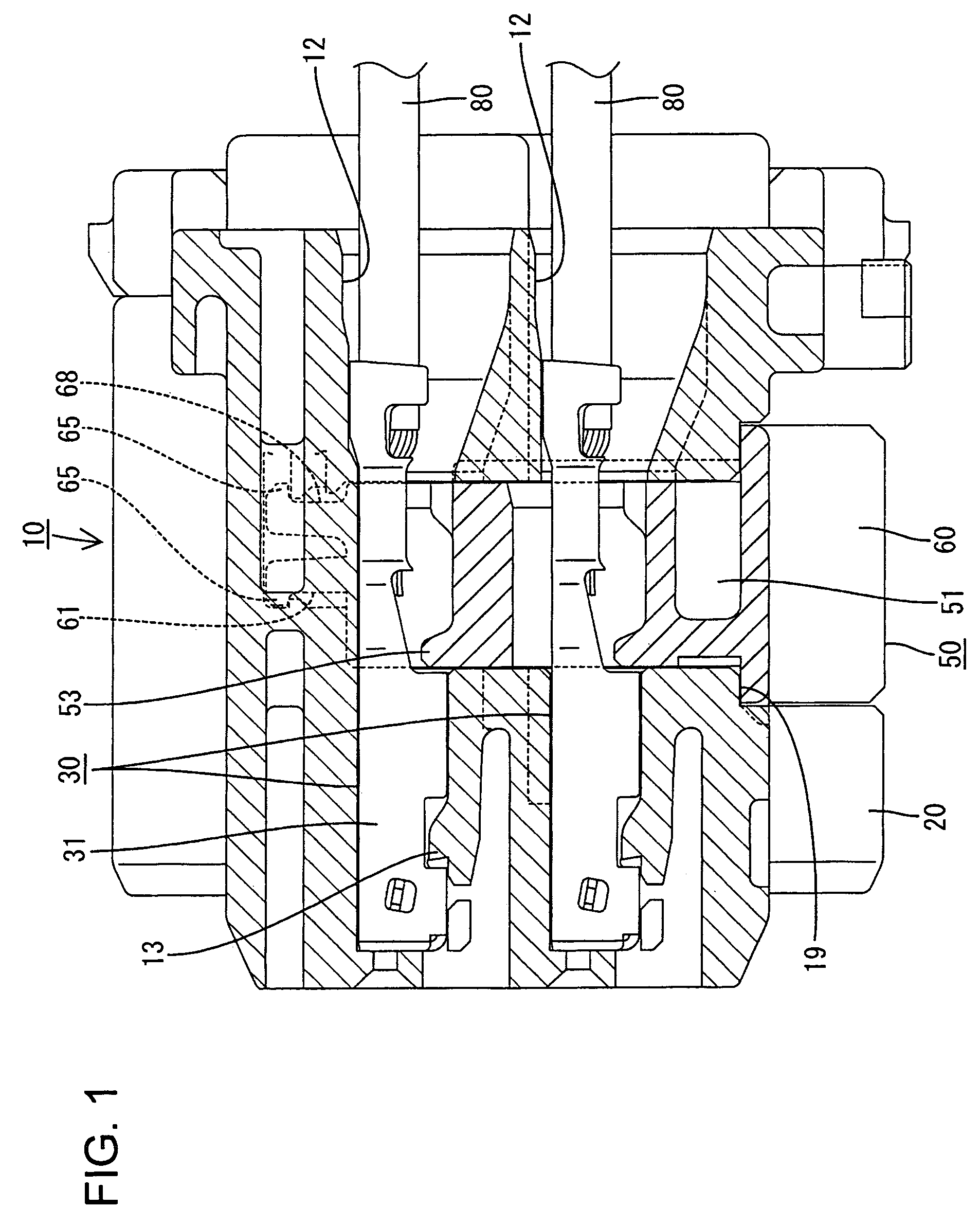
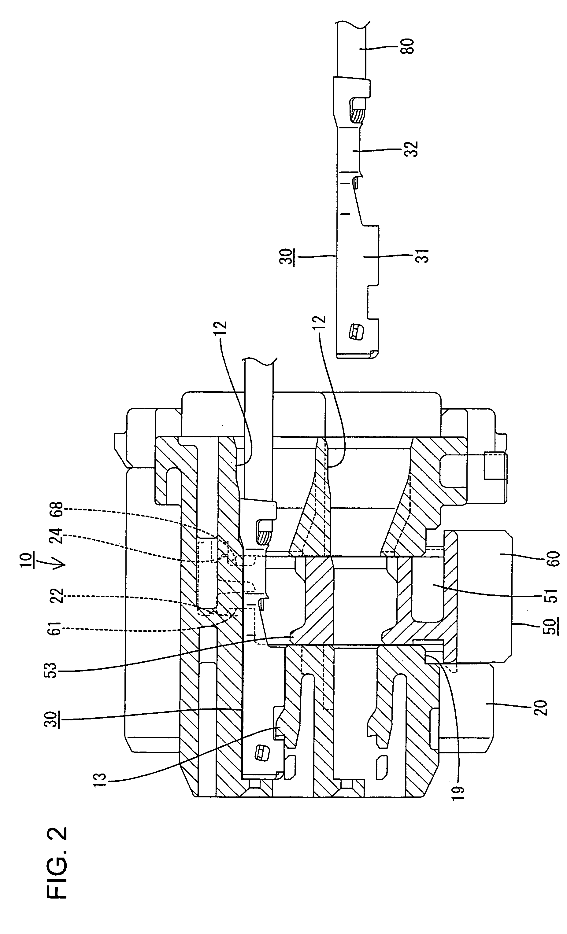
[0028]A female connector according to the invention includes a housing identified generally by the numeral 10 in FIGS. 1 through 13. The housing 10 is molded unitarily from a synthetic resin and has opposite front and rear ends. The front end of the housing 10 is at the left side in FIG. 1, and is configured to mate with a male connector (not shown). The term vertical is used herein as a convenient frame of reference and refers to the orientation of the housing 10 shown in FIG. 1.

[0029]Right and left locking projections 11 are formed on the opposite right and left sides of the housing 10, as shown in FIG. 7, and are configured to be locked to the male connector. Cavities 12 extend from the rear end of the housing 10 towards the front end and are arranged side-by-side in upper and lower stages. A female terminal fitting 30 can be inserted into each cavity 12 from the rear end of the housing 10. A resiliently deformable lance 13 is cantilevered forwardly from the bottom wall of each c...


PUM


Abstract

A connector has a housing (10) with cavities (12) for accommodating terminal fittings (30). A retainer-mounting hole (17) is formed in a side of the housing (10) and communicates with the cavities (12). A retainer (50) can be mounted in the retainer-mounting hole (17) at a predetermined normal depth to lock the terminal fittings (30) in the cavities (12). The retainer (50) has side locks (61) at both sides of the retainer (50) that lock to a corresponding side to-be-locked surface (22) in the housing (10). The retainer (10) also has an intermediate lock (68) at a central position of the retainer (50) that locks to an intermediate to-be-locked surface (22) in the housing (10). The blocking strength of the intermediate lock (68) exceeds the locking strength of the side locks (61).

Description

BACKGROUND OF THE INVENTION[0001]1. Field of the Invention[0002]The present invention relates to a connector having a retainer.[0003]2. Description of the Related Art[0004]U.S. Pat. No. 5,947,775 discloses a connector with a housing that has cavities for receiving terminal fittings. The connector also has a retainer that is made of a synthetic resin. The retainer has a base with opposite left and right ends and left and right side plates that project from the respective left and right ends of the base. The side plates retainer can be mounted to the housing in a direction transverse to the insertion direction of the terminal fittings into the cavities. Thus, locks on the side plates of the retainer engage to-be-locked portions on side walls of the housing to hold the retainer in a position where the base of the retainer engages the terminal fittings to retain the terminal fittings in the cavities.[0005]The multi-polarity of connectors has led to a plurality of cavities arranged in a ...

Claims


Application Information

Patent Timeline
Patent Type & Authority Patents(United States)
IPC IPC(8): H01R13/514
CPCH01R13/4362
Inventor YAMASHITA, KAZUNORIYAMAKADO, TOSHIO
Owner SUMITOMO WIRING SYST LTD
Why Eureka
Try Eureka