Constant velocity joint vent

a constant velocity, joint technology, applied in the direction of yielding couplings, clutches, rotary machine parts, etc., can solve the problems of joint failure, vibration and noise source, and hinder its function,

Active Publication Date: 2007-04-17
GKN DRIVELINE NORTH AMERICA
View PDF15 Cites 15 Cited by
  • Summary
  • Abstract
  • Description
  • Claims
  • Application Information

AI Technical Summary

Benefits of technology

[0014]It is a principal object of the present invention to provide a system for venting a constant velocity joint without loss of grease or other internal joint lubricant.
[0016]It is a further object of the present invention to provide such a system for venting a constant velocity joint which prevents water, dirt and other contaminants which may inhibit joint operation from entering the joint.

Problems solved by technology

Plunging tripod universal joints allow the interconnection shafts to change length during operation without the use of splines which provoke significant reaction forces thereby resulting in a source of vibration and noise.
However, when the constant velocity joint is in a static state and not rotating, grease may settle in the vent hole, blocking it and hindering its function.
This condition may create a pressure buildup and possibly result in joint failure due to a ruptured boot, among other things.
During this static state, grease may also flow from the vent hole and out of the joint, thereby resulting in the loss of grease from the joint.
This loss of lubricant could possibly lead to more frequent relubrication and maintenance, and eventually possible replacement of the joint.
Still further, in off road, submerged, or other severe weather vehicle conditions, water and other contaminants may enter the joint through the vent hole and impair joint operation.
However, this vent hole may still be subject to grease buildup during a static state or operative state.

Method used


Image

  • Constant velocity joint vent
  • Constant velocity joint vent
  • Constant velocity joint vent

Examples


Embodiment Construction

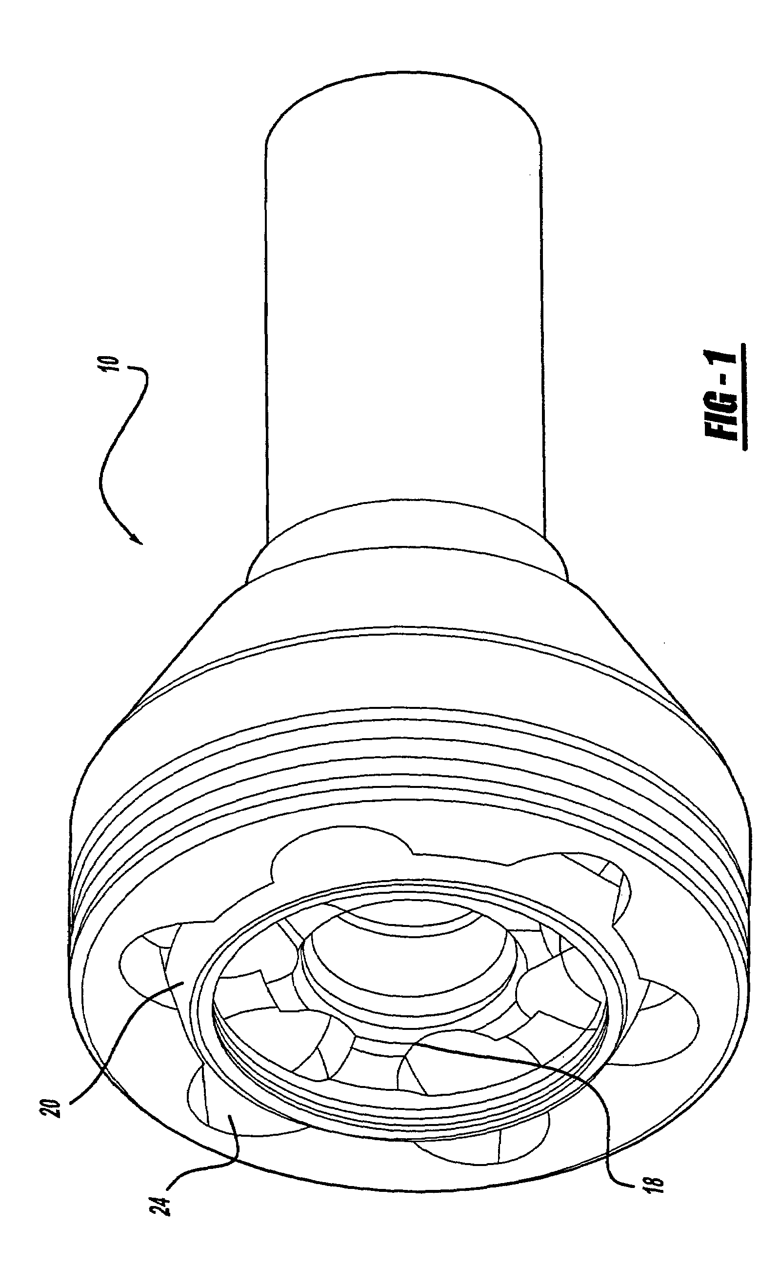
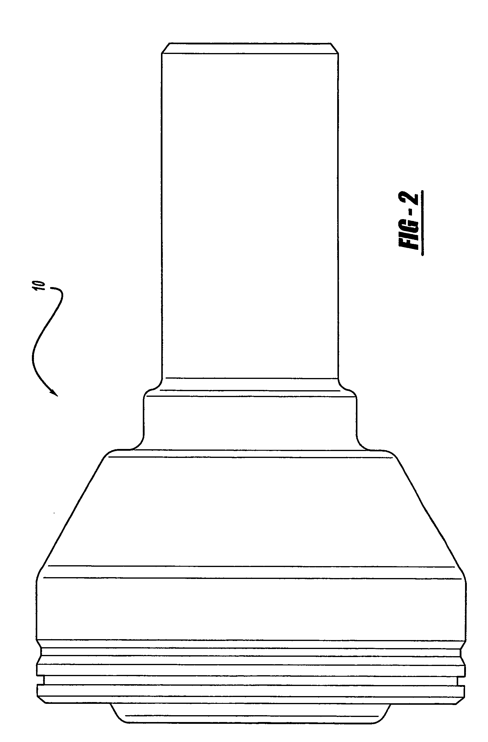
[0036]Referring now to FIGS. 1–4, there is shown generally a monoblock type of universal joint and more specifically a constant velocity universal joint 10 of the fixed or Rzeppa type. Constant velocity joint 10 comprises an inner race 18, a cage 20, balls 22 and outer race 24 disposed within the joint chamber 25. As those skilled in the art will recognize, usually six balls 22 are used with the constant velocity joint 10. It should be noted that any of the other known types of constant velocity joints may also be used with the present invention.

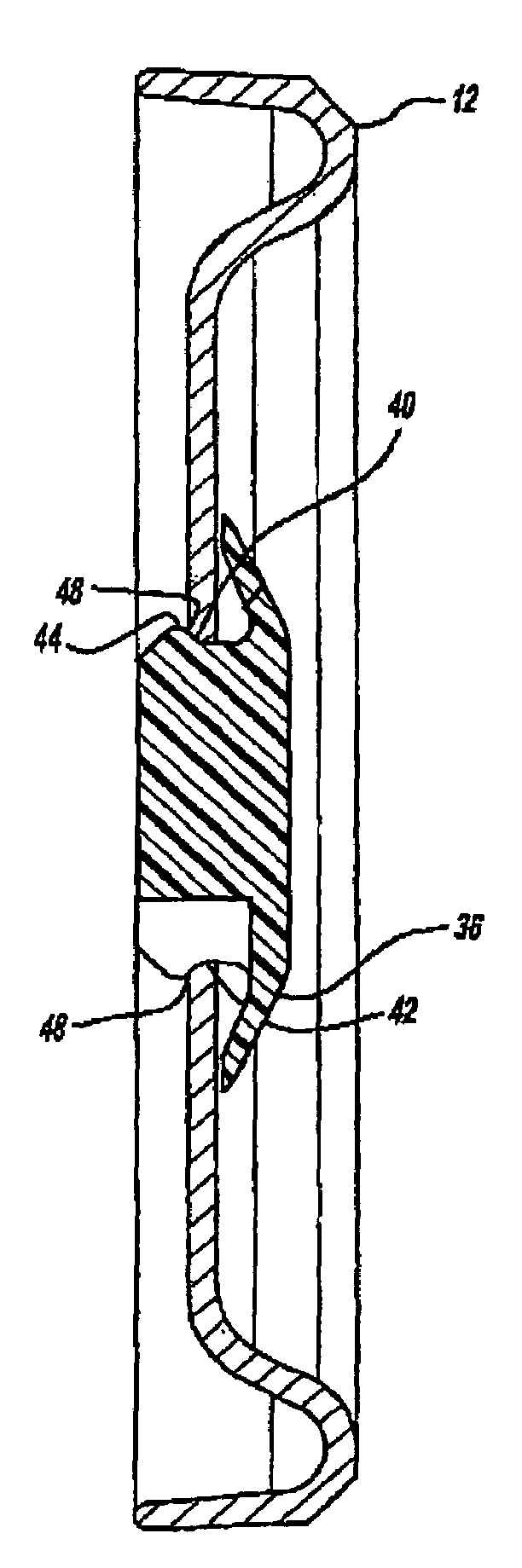
[0037]As shown in greater detail in FIGS. 5–13, a vent plate 12 (also called a breather plate) is disposed within constant velocity joint 10 and defines a vent aperture 14 adapted to receive a vent valve 16. Vent plate 12 may be any suitable size or shape depending on the application. However, in the preferred embodiment shown, venting plate 12 comprises an annular member adapted to be disposed in the closed end 26 of constant velocity joint...


PUM


Abstract

A vent valve for use in a constant velocity joint having a vent aperture in communication with a joint cavity comprises a body portion having a first end and a second end and a plurality of escape pathways extending therebetween. An umbrella shaped flexible retention cap is disposed adjacent the first end of the body portion and the plurality of escape pathways, wherein the retention cap is operative in a normally closed position to cover the plurality of escape pathways and seal the joint from external contaminants, and in response to internal pressure created in the joint cavity functions to bellow outward and expose the plurality of escape pathways to permit air to escape from the cavity.

Description

TECHNICAL FIELD[0001]The present invention relates to an improved venting constant velocity universal joint, and more specifically to a constant velocity joint vent.BACKGROUND ART[0002]Most constant velocity universal joints are sealed in order to retain grease inside the joint while keeping contaminants and foreign matter, such as dirt, water, and the like out of the joint. In order to achieve this protection, the constant velocity joint is usually enclosed at the open end of the outer race by a sealing boot made of rubber, thermoplastic or urethane. The opposite end of the outer race is sometimes formed by an enclosed dome known in the art as a “grease cap”. Such sealing and protection of the constant velocity joint is necessary because, once the inner chamber of the outer joint is partially-filled and thus lubricated, it is generally lubricated for life.[0003]It is often necessary to vent the constant velocity joint in order to minimize air pressure fluctuations due to expansion ...

Claims


Application Information

Patent Timeline
Patent Type & Authority Patents(United States)
IPC IPC(8): F16D3/223F16D3/22F16D1/00F16D3/20F16D3/84F16K24/00
CPCF16D3/84Y10T464/10Y10S464/906F16D2300/0212F16D2003/846
Inventor WANG, SHEN-LING ALLEN
Owner GKN DRIVELINE NORTH AMERICA
Why Eureka
Try Eureka