Energy collection and storage system

a technology of energy collection and storage system, which is applied in the direction of electric generator control, process and machine control, instruments, etc., can solve the problems of inability to output constant levels of power, energy output decline, and inability to readily commercialize or integrate with existing man-portable electronic devices

Inactive Publication Date: 2007-04-17
GREAT SYST
View PDF76 Cites 46 Cited by
  • Summary
  • Abstract
  • Description
  • Claims
  • Application Information

AI Technical Summary

Benefits of technology

[0005]This invention relates to a field power generation and energy storage device that can utilize numerous natural and artificially produced kinetic energy sources to create mechanical kinetic energy which is then stored, preferably in one or more spring configurations, and can later be released on demand to create electric power or do other mechanical work. More specifically the preferred version describes a kinetic energy input and storage system that can utilize rotational kinetic energy, or linear kinetic energy converted into rotational energy, which is transferred as mechanical energy to drive a gear system that winds one or more constant force spring motors. The spring motors utilize a restraining (pawl) mechanism to hold the power in compressed spring format until needed. The stored energy can be released on demand. The release of the stored spring energy provides a high torque rotational force that is configured through a second integral gear system into a lower torque, but higher high speed rotational force which is used to do work, primarily in the form of spinning a generator to produce electrical power. The generation of electrical power, once conditioned, rectified or modulated can supply a direct feed to output terminals on a control panel to meet output load requirements or can be channeled to an internal or external storage battery where it can be used for on-demand distribution at a lower output rate over an extended timeframe. Additionally and more specifically, an energy system as described above having a self adjusting and self-regulating control circuitry that switches output power from the direct spring motor driven generator output to storage battery source output when the spring motor is near depletion so that the spring motor can be recharged with kinetic energy while the storage battery continues to output electrical power. The battery system will continue to supply power until the control circuitry of the invention senses the spring motor is recharged and is again capable of taking over the generation of a direct output of energy via spinning generator to produce energy to power a load on the system. In this manner the Invention can supply a continuous stream of electrical energy without disruption while still allowing the Invention to be recharged itself without disrupting the output energy flow.
[0015]Man-Portable: The Invention's small size and weight allow the Invention to be carried and used by a single person. Because power is important to individuals in many remote and hazardous situations, the ability for one person to carry and use the Invention creates a very useful portable device.

Problems solved by technology

As portable electronic devices proliferate, the problem of having a source of power that is steady and reliable confronts everyone, including consumers, industry, the government and the military.
Although research is underway on fuel cells, they have not yet reached the point where they can be readily commercialized or integrated with existing man-portable electronic devices.
As the power of the single clock-type expansion spring winds down in these devices the energy output diminishes.
Thus due to their design they do not have the ability to output constant levels of power over the output time of the spring.
Additionally, current products using any type of spring power system have a gap between their ability to produce power or run their imbedded components.
The springs wind down and the energy stops whereupon the user is forced to rewind the spring while no power is available for continued operations of the device.
Current designs also do not allow for the charging of multiple internal springs to store a larger reserve of energy than the single spring holds, nor do the current designs allow for discharging the spring while simultaneously charging one or more additional springs in a bank of springs.
Additionally, the current products on the market do not have the ability to use multiple kinetic energy input sources to charge their spring energy sources, nor can they deliver the energy input to their systems in any way other than the manual winding of their single full rotation clock-type spring format around which they are designed.

Method used


Image

  • Energy collection and storage system
  • Energy collection and storage system
  • Energy collection and storage system

Examples


Embodiment Construction

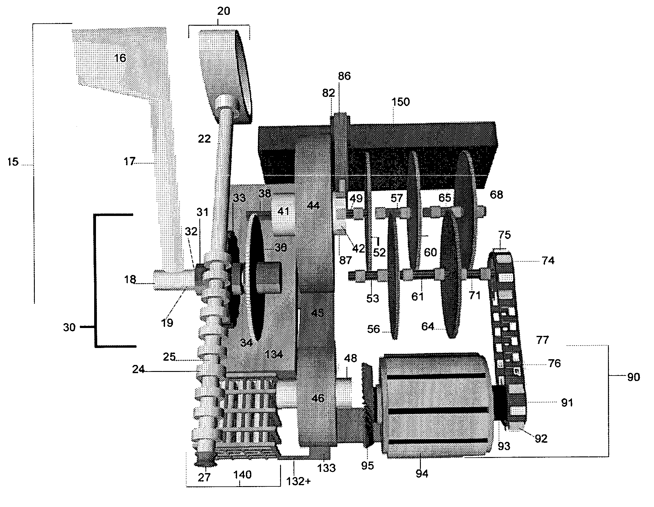
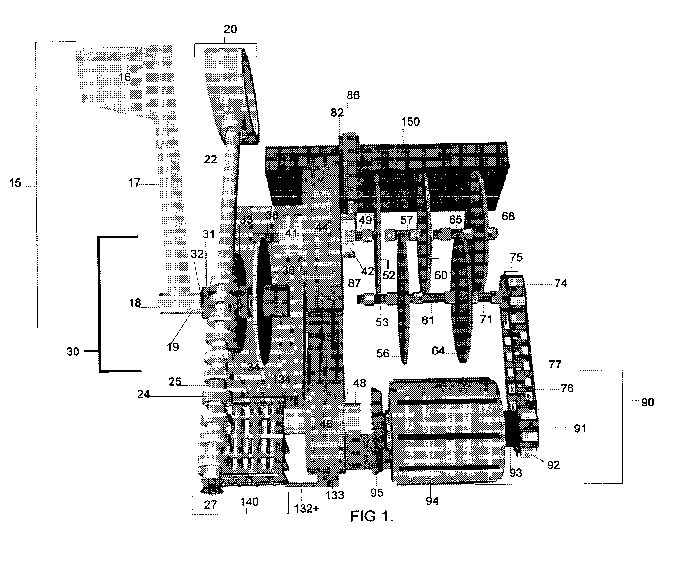
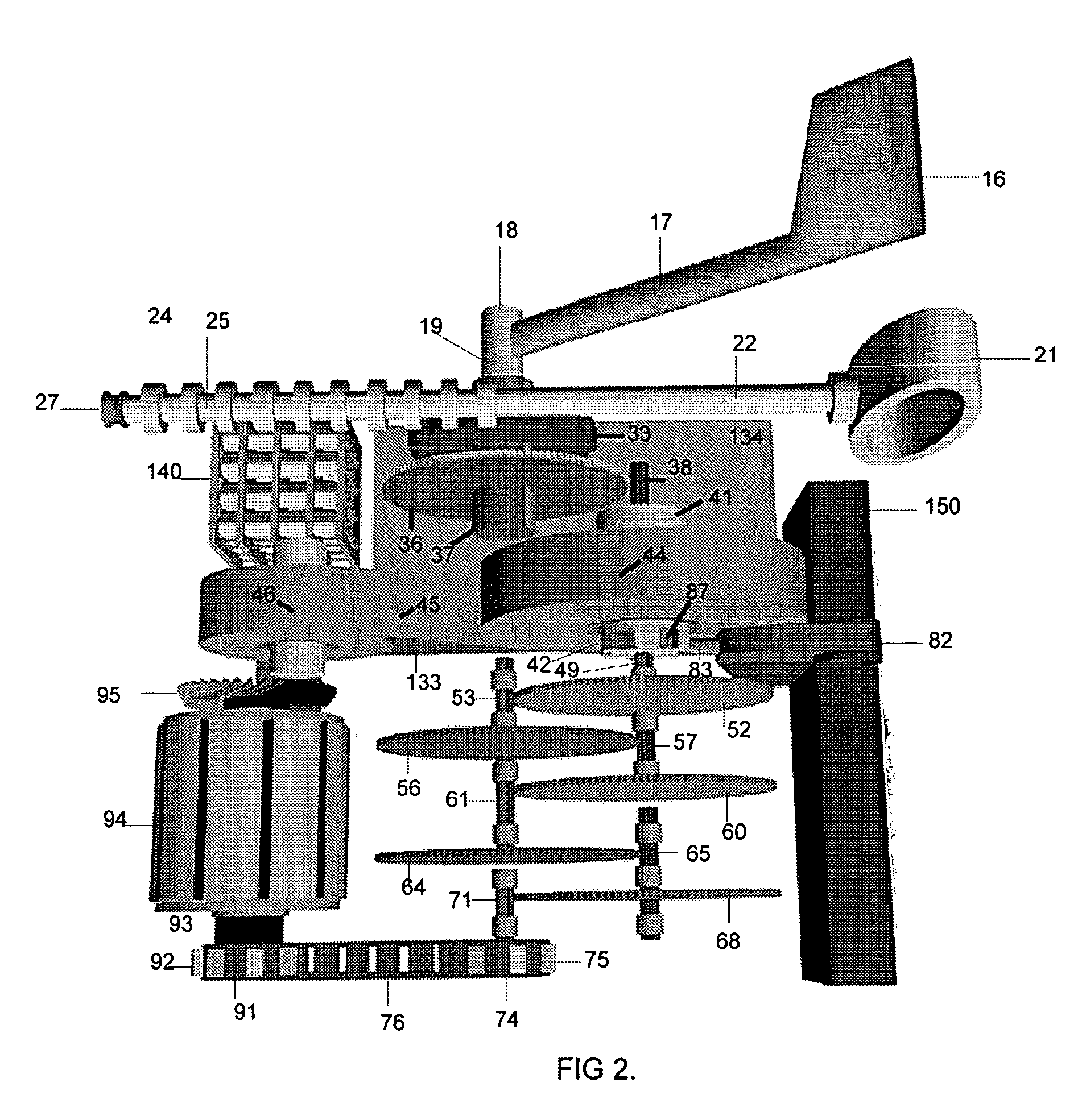
[0037]The current invention is a compact device that has several integrated mechanical subsystems that work together to create a device for the collection, storage and / or delivery of kinetic energy that can later be released on demand to do work. The invention can utilize its stored kinetic energy to perform various types of work. The invention can utilize one of several types of available kinetic energy inputs to charge the invention's storage system. Among the inputs that can be utilized is the physical energy of the user via body mechanics using the hand, foot or other body part to deliver pressure to a lever, pulley or linear rod that winds the gear system. Additional inputs also include the use of pulsed hydraulic pressure, compressed gas or an explosive cartridge to produce expanding gases to drive a piston or other linkage connected to the gearing to charge the system. The input energy is then stored in one or more constant force spring motors that are capable of accepting th...


PUM


Abstract

A power generation and / or storage device utilizes human motion inputs or other power sources (i.e. hydraulics, pneumatics or explosive gases) to create mechanical kinetic energy that is stored (preferably in springs) and later released on demand to rotate a generator to produce electricity.

Description

CROSS-REFERENCE TO RELATED APPLICATIONS[0001]This application is a continuation of U.S. patent application Ser. No. 11 / 054,852 filed 10 Feb. 2005 (now U.S. Pat. No. 7,009,350), which in turn claims priority under 35 USC § 19(e) to U.S. Provisional Patent Application 60 / 544,696 filed 13 Feb. 2004 and 60 / 579,532 filed 14 Jun. 2004, the entireties of which are incorporated by reference herein.FIELD OF THE INVENTION[0002]This invention relates to a man-portable field power generation and energy storage device that can utilize numerous natural and artificially produced kinetic energy sources to create mechanical kinetic energy which is then stored and released on demand to create electric power or do other mechanical work.BACKGROUND OF THE INVENTION[0003]As portable electronic devices proliferate, the problem of having a source of power that is steady and reliable confronts everyone, including consumers, industry, the government and the military. At present, only batteries are available ...

Claims


Application Information

Patent Timeline
Patent Type & Authority Patents(United States)
IPC IPC(8): H02P7/32
CPCH02P9/48
Inventor GOLD, ROBERT J.
Owner GREAT SYST
Why Eureka
Try Eureka