Apparatus for assisting in the removal and installation of vehicle components

a technology for vehicle components and accessories, applied in the direction of elevators, transportation items, manufacturing tools, etc., can solve the problems of not being able to adjust the position of the device, the device is not well-suited for use in connection with other automobile body parts such as bumpers, deck lids and hoods, and the device is not easy to opera

Active Publication Date: 2007-04-24
BSB INNOVATIONS LLC
View PDF4 Cites 6 Cited by
  • Summary
  • Abstract
  • Description
  • Claims
  • Application Information

AI Technical Summary

Benefits of technology

[0006]It is a further object to provide an apparatus that is adjustable along three separate axes to allow precise positioning of the automobile body part at the time of installation or removal.

Problems solved by technology

While such devices perform well in the removal and installation of automobile doors, their size and configuration are not well suited for use in connection with other automobile body parts such as bumpers, deck lids and hoods.
That device works well for truck beds, but lacks any mechanism to adjust the position of the truck bed once it has been removed.
Further, the truck bed lifter, because of its size and configuration, is not well suited for use in connection with other automobile parts such as doors, hood, deck lids, bumpers and the like.
Thus, none of the prior art devices are versatile enough to be used to install and / or remove a variety of automobile body parts including hoods, doors, deck lids and bumpers.
Further, none of the prior art devices provide a tool that is adjustable along three separate axes and can be quickly and easily affixed to a lifting device such as an engine hoist.

Method used


Image

  • Apparatus for assisting in the removal and installation of vehicle components
  • Apparatus for assisting in the removal and installation of vehicle components
  • Apparatus for assisting in the removal and installation of vehicle components

Examples


Embodiment Construction

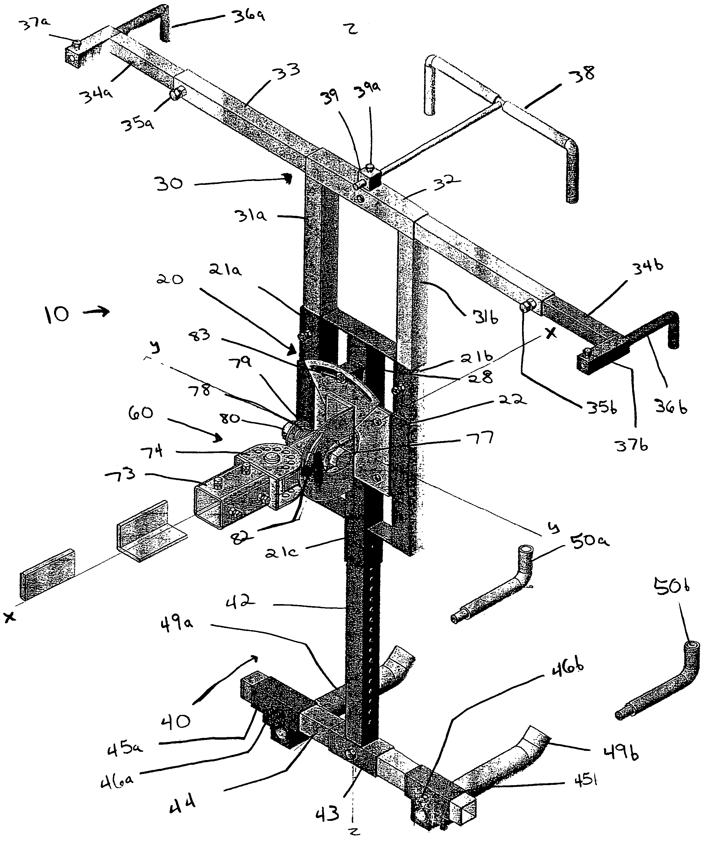
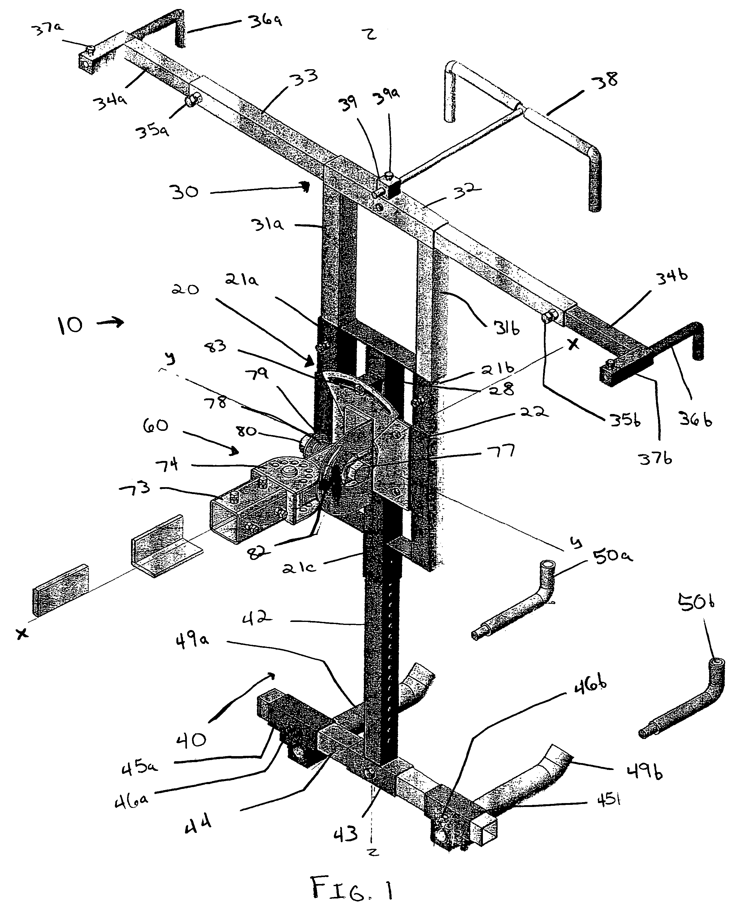
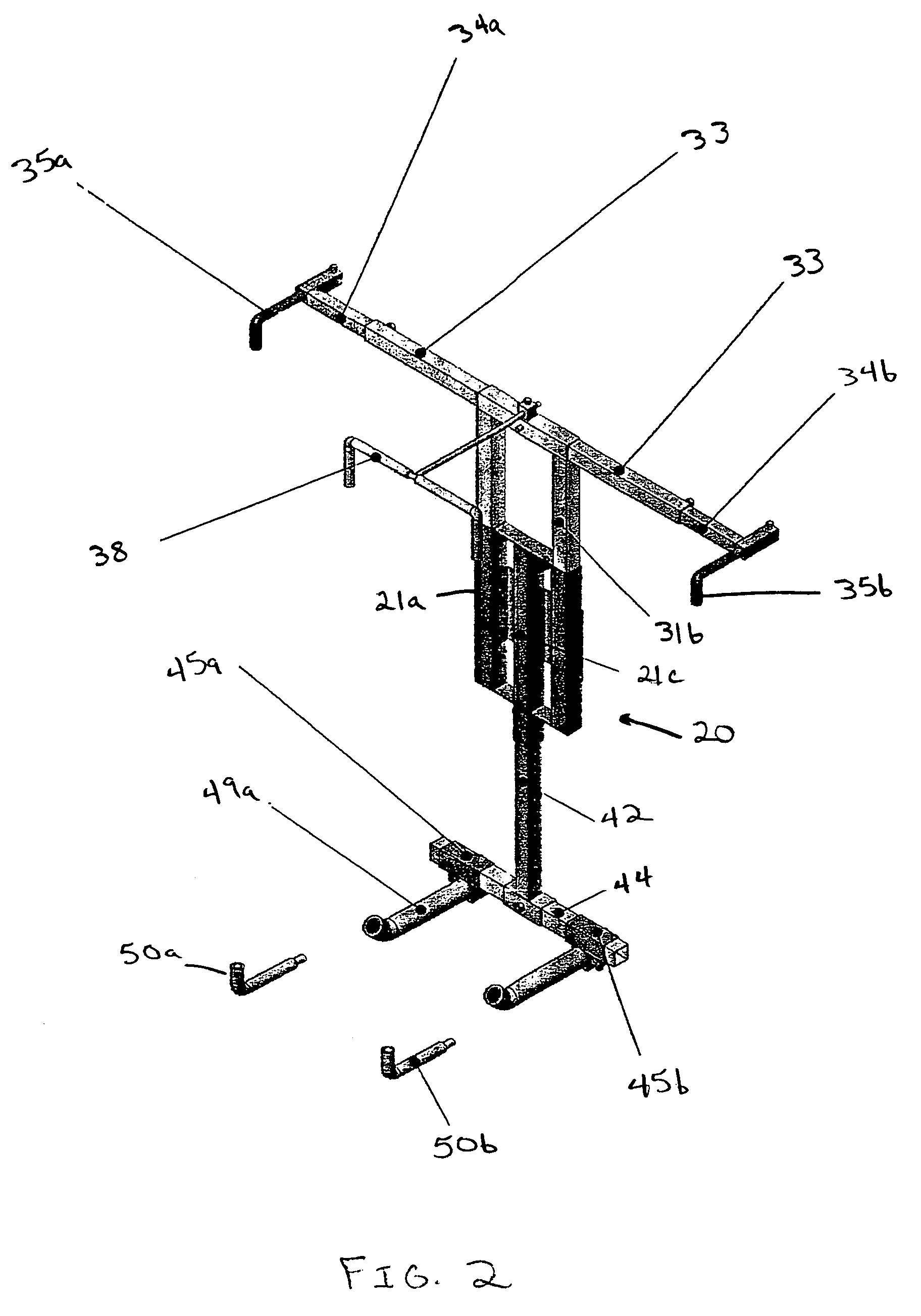
[0038]Referring now to the drawings and, in particular, to FIG. 1 and FIG. 2, there is shown in a preferred embodiment of my invention, a component handling apparatus 10 for assisting in the removal and installation of vehicle components, such as hoods, doors, bumpers and the like. The component handling apparatus 10 preferably includes a central telescoping fixture assembly 20, an upper telescoping tube assembly 30, a lower telescoping tube assembly 40, and an articulating arm assembly 60.

[0039]As most clearly shown in FIG. 3, the central telescoping fixture assembly 20 includes three parallel tubes 21a, 21b, 21c secured together by a mounting plate 22 on a rear face thereof. In addition, the tubes are secured together at their respective upper ends by a reinforcing bar 23, which is secured to the tubes such that the two outer tubes 21a, 21b remain open at the upper end thereof. Similarly, the tubes are secured together at or near their respective lower ends by one or more lower re...


PUM


Abstract

An improved apparatus for assisting in the removal and installation of vehicle components such as doors, hoods, deck lids, bumpers and / or the like during assembly, disassembly and / or repair by using an expandable metal fixture attached to a portable engine hoist is provided. The apparatus includes a central telescoping fixture assembly formed of a plurality of parallel tubes secured together by a mounting plate on the rear face thereof. An upper telescoping tube assembly is provided comprising one or more tubes having a first end slidably engaging and extending outwardly from the central fixture assembly tubes and second ends affixed to a cross bar assembly. Also provided is a lower telescoping tube assembly comprising a tube having a first end slidably engaging and extending outwardly from a central fixture assembly tube and a second end affixed to a cross bar assembly. An articulating arm subassembly is provided to connect the central telescoping fixture assembly to a lifting apparatus such as an engine hoist. The articulating arm assembly permits the position of the device to be altered and removably fixed in relation to three separate axes.

Description

BACKGROUND OF THE INVENTION[0001]This invention relates generally to an apparatus for assisting in the removal and installation of vehicle components. More specifically, this invention relates to a device for supporting automotive vehicle doors, hoods, deck lids, bumpers and / or the like during assembly, disassembly and / or repair by using an expandable metal fixture attached to a portable engine hoist.[0002]A variety of different devices have been used to assist individual users in removal and installation of doors, hoods, deck lids and bumpers during automobile repair and / or restoration projects. Door dollies, such as those manufactured by Brut Manufacturing Co., have previously been used to remove and install automobile doors during repair and restoration projects. While such devices perform well in the removal and installation of automobile doors, their size and configuration are not well suited for use in connection with other automobile body parts such as bumpers, deck lids and ...

Claims


Application Information

Patent Timeline
Patent Type & Authority Patents(United States)
IPC IPC(8): B66B3/00
CPCB25H1/0007B66C1/107B66C1/62
Inventor CRAWFORD, EARL F.
Owner BSB INNOVATIONS LLC
Why Eureka
Try Eureka