Compressor for an aircraft engine

a compressor and aircraft engine technology, applied in the direction of liquid fuel engine components, supersonic fluid pumps, non-positive displacement fluid engines, etc., to achieve the effect of reducing blade vibration

Active Publication Date: 2007-04-24
ROLLS ROYCE DEUT LTD & CO KG
View PDF24 Cites 25 Cited by
  • Summary
  • Abstract
  • Description
  • Claims
  • Application Information

AI Technical Summary

Benefits of technology

[0004]It is a broad aspect of the present invention to provide a compressor design which prevents damage or life reduction of the compressor disk and the compressor blades.
[0007]A mechanism which, according to the present invention, provides surface roughness and is arranged on the suction side of the compressor blades at a certain distance from and essentially parallel to the blade leading edge was unexpectedly found to be capable of reducing the stress on the compressor disk. Comprehensive investigations yielded that unexpectedly strong natural frequencies of the individual blades, i.e. second and third bending mode and first torsional mode, occur under certain flight conditions characterized by flight altitude, flight velocity, Reynolds number and Strouhal number which are transferred via the blade root to the compressor disk and cause damage to the latter. The intent of the arrangement for the fixation of the flow transition on the suction side at a certain distance to the blade leading edge is to prevent, or limit, oscillation of the compression shocks, which are known to act upon the blade surface, and thus to suppress the coupling effect between the oscillating compression shocks and the natural frequencies (second and third bending mode, first torsional mode of the blade) which amplifies the natural frequencies to such an extent that the above-mentioned damage occurs. The inventive concept is to prevent, or limit, the periodic movement of the compression shocks and their reaction on the natural frequencies by fixation of the flow transition, restricting the change-over point from the laminar to the turbulent boundary layer flow upstream of the compression shock, i.e. preventing it from oscillating, locally on the suction side, to such an extent that the oscillating movement of the compression shocks and their vibration-amplifying effect on the natural frequencies of the blades, irrespective of the operating range of the compressor blades, is avoided. Thus, compressors with compressor blades can be made available which will not be damaged by the above-described, specific flight conditions.
[0009]The compressor provided with the flow transfer fixation according to the present invention both satisfies all aerodynamic requirements and has long life and essentially unchanged mass. The mechanism described in the above will be located and dimensioned such that the surge characteristics are not affected or that they are even improved. Similarly, the performance data of the blading will not, or only hardly, be affected. In the range of high Reynolds numbers, typically 8.0×10⁶ to 5.0×10⁷, positioning and dimensioning will be such that the behavior of the compressor blade as regards surge and stall is not affected. In the range of small Reynolds numbers, typically 0.5×10⁶ to 8.0×10⁶, positioning and dimensioning will be such that, on the one hand, blade vibration is reduced and, on the other hand, the behavior of the compressor blade as regards surge and stall is not affected.

Problems solved by technology

Comprehensive investigations yielded that unexpectedly strong natural frequencies of the individual blades, i.e. second and third bending mode and first torsional mode, occur under certain flight conditions characterized by flight altitude, flight velocity, Reynolds number and Strouhal number which are transferred via the blade root to the compressor disk and cause damage to the latter.

Method used


Image

  • Compressor for an aircraft engine
  • Compressor for an aircraft engine
  • Compressor for an aircraft engine

Examples


Embodiment Construction

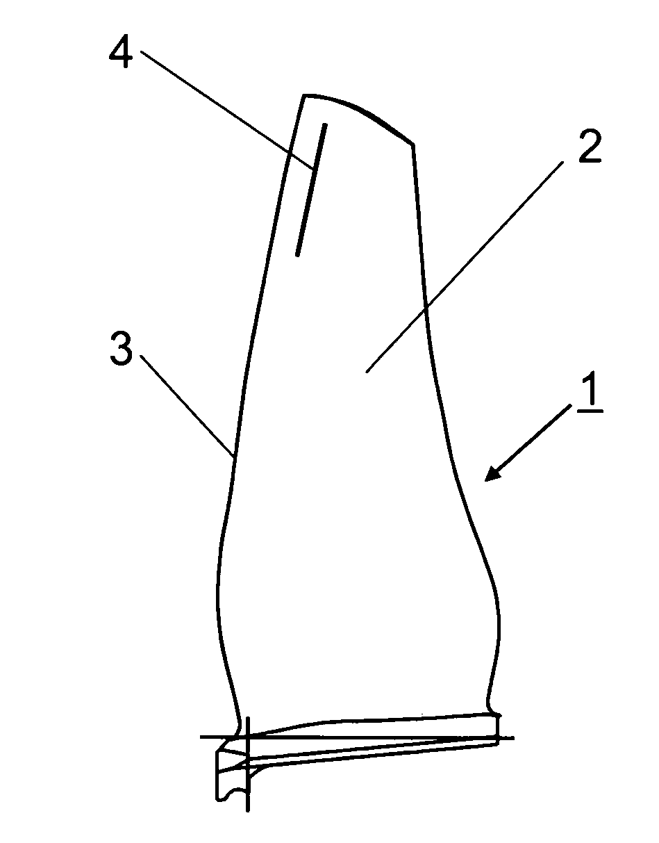
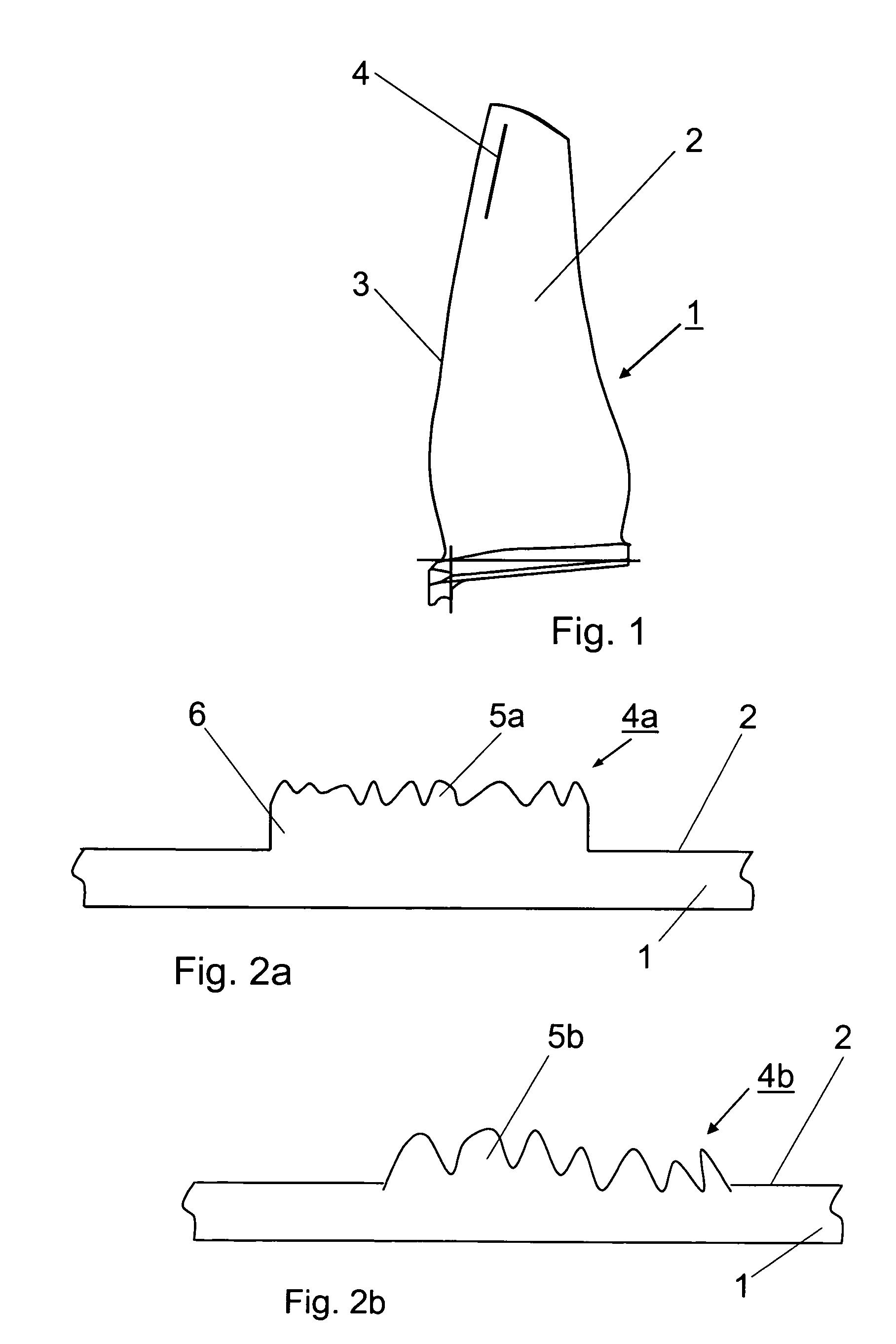
[0014]FIG. 1 shows a compressor blade 1 at which a long flow transition fixation mechanism 4 is provided on the suction side 2 at a short distance to the leading edge 3. The flow transition fixation mechanism 4 extends approximately parallel to the leading edge 3 in the upper third of the compressor blade 1. Several such compressor blades 1 are attached to the circumference of the compressor disk (not shown).

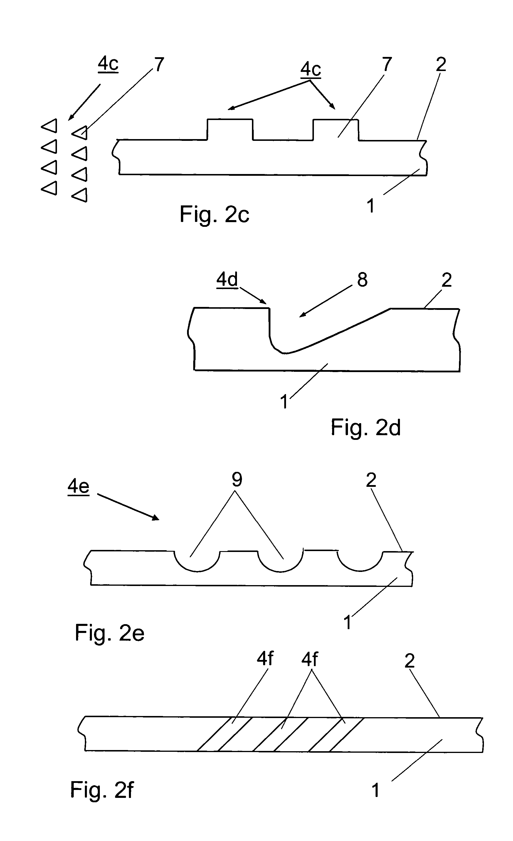
[0015]The flow transition fixation mechanism 4 comprises, as shown in FIGS. 2a to 2f, a long area of roughness of varying form provided on the suction side of the compressor blade 1. The drawing shows various examples of the flow transition fixation mechanism 4. The flow transition fixation mechanism 4a shown in FIG. 2a is, on its surface, firmly bonded to a fine-grained material 5a of a certain grain size. A grainy material retained in a binder 6, which must be erosion-resistant, can here be used. In the variant according to FIG. 2b, the flow transition fixation mechanism 4b is...


PUM


Abstract

On a compressor with compressor blades, a flow transition fixation mechanism (4) is provided on the suction side (2), approximately parallel to the leading edge (3) and upstream of the compression shocks acting upon the blade, which prevents the transition point from the laminar to the turbulent boundary layer flow from oscillating, thus suppressing oscillation of the compression shocks and their coupling effect with the natural frequencies of the compressor blades.

Description

[0001]This application claims priority to European Patent Application EP04090120.9 filed Mar. 25, 2004, the entirety of which is incorporated by reference herein.BACKGROUND OF THE INVENTION[0002]This invention relates to a compressor for an aircraft engine with compressor blades attached to the compressor disk, in particular compressor blades with a small span-chord ratio.[0003]Compressors with compressor blades having a large chord length, but with a reduced number of blades, are known to be used on certain aircraft engines. While this type of compressor has certain advantages over the former designs, this new blade was found to give rise to unexpected stresses in the compressor disk to which it is attached.BRIEF SUMMARY OF THE INVENTION[0004]It is a broad aspect of the present invention to provide a compressor design which prevents damage or life reduction of the compressor disk and the compressor blades.[0005]It is a particular object of the present invention to provide solution ...

Claims


Application Information

Patent Timeline
Patent Type & Authority Patents(United States)
IPC IPC(8): F04D21/00B64D33/00F01D5/14F01D5/16F01D5/20F04D29/66F04D29/68
CPCF01D5/145F01D5/16F04D29/668F04D29/681Y02T50/673F05D2240/31F05D2260/96F04D29/324Y02T50/60F05D2300/516
Inventor JOHANN, ERIK
Owner ROLLS ROYCE DEUT LTD & CO KG
Why Eureka
Try Eureka