Process for fabricating MEMS membrane with integral mirror/lens

a technology of mirrors and mems membranes, applied in mechanical recording, instruments, record information storage, etc., can solve problems such as the change of the reflector separation of the fp filter or the cavity length

Inactive Publication Date: 2007-04-24
EXCELITAS TECH
View PDF9 Cites 109 Cited by
  • Summary
  • Abstract
  • Description
  • Claims
  • Application Information

AI Technical Summary

Problems solved by technology

This results in changes in the reflector separation of the FP filter or cavity length in the case of a laser.

Method used


Image

  • Process for fabricating MEMS membrane with integral mirror/lens
  • Process for fabricating MEMS membrane with integral mirror/lens
  • Process for fabricating MEMS membrane with integral mirror/lens

Examples


Embodiment Construction

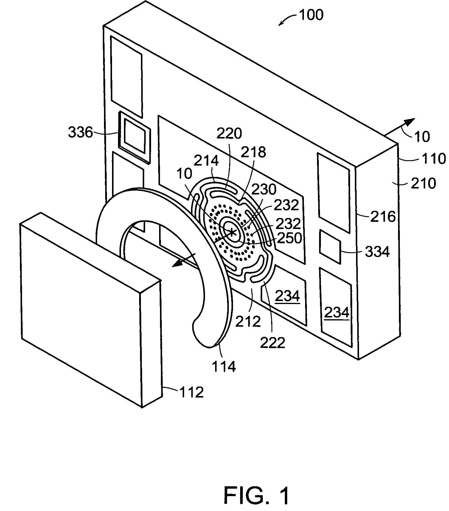
[0025]FIG. 1 shows a Fabry-Perot tunable filter 100 comprising an optical membrane device 110, which has been constructed according to the principles of the present invention.

[0026]Generally, in the FP filter 100, a spacer device 114 separates the mirror device 112 from the membrane device 110 to thereby define a Fabry-Perot (FP) cavity.

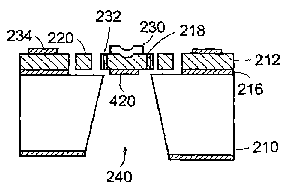
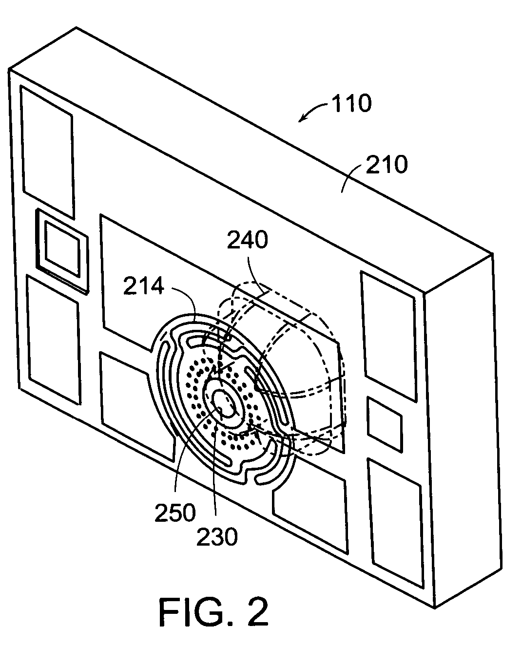
[0027]The optical membrane device 110 comprises handle material 210 that functions as a support. Preferably, the handle material is wafer material such as from a silicon handle Wafer, which has been subsequently singulated into the illustrated device.

[0028]An optical membrane or device layer 212 is added to the handle wafer material 210. The membrane structure 214 is formed in this optical membrane layer 212. In the current implementation, the membrane layer 212 is silicon. An insulating layer 216 separates the optical membrane layer 212 from the handle wafer material 210.

[0029]During manufacture, the insulating layer 216 functions as a sacrificial / r...


PUM


Abstract

An optical membrane device and method for making such a device are described. This membrane is notable in that it comprises an optically curved surface. In some embodiments, this curved optical surface is optically concave and coated, for example, with a highly reflecting (HR) coating to create a curved mirror. In other embodiments, the optical surface is optically convex and coated with, preferably, an antireflective (AR) coating to function as a refractive or diffractive lens.

Description

BACKGROUND OF THE INVENTION[0001]Micro-optical electromechanical system (MEOMS) membranes are used in a spectrum of optical applications. For example, they can be coated to be reflective and then paired with a stationary mirror to form a tunable Fabry-Perot (FP) cavity / filter. They can also be used as stand-alone reflective components to define the end of a laser cavity, for example.[0002]Typically, membrane deflection is achieved by applying a voltage between the membrane and a fixed electrode. Electrostatic attraction moves the membrane in the direction of the fixed electrode as a function of the applied voltage. This results in changes in the reflector separation of the FP filter or cavity length in the case of a laser.[0003]In optical systems, these membranes have advantages over cantilevered structures, for example. Membranes better maintain parallelism through the range of their deflection and tend to be more mechanically robust and have fewer relevant vibration modes.[0004]In...

Claims


Application Information

Patent Timeline
Patent Type & Authority Patents(United States)
IPC IPC(8): H01L21/00G02B5/18G02B26/00G02B26/02G02B26/08
CPCG02B5/1828G02B26/001G02B26/02G02B26/0833G02B26/0875
Inventor FLANDERS, DALE C.NAGLE, STEVEN F.STERN, MARGARET B.
Owner EXCELITAS TECH
Why Eureka
Try Eureka