
Bi-directional switch apparatus with electric guitar applications

a switch apparatus and electric guitar technology, applied in the direction of electric switches, electrical devices, instruments, etc., can solve the problems of poor visual representation of the settings, less intuitive operation, and inferiority of the application, and achieve the effect of simplifying, comprehensive and rapid operable control of the guitarist, and expanding the functionality of the selector switch

Active Publication Date: 2007-04-24
BRYCE ALASDAIR JAMES
View PDF9 Cites 20 Cited by
  • Summary
  • Abstract
  • Description
  • Claims
  • Application Information

AI Technical Summary

Benefits of technology

The compound selector switch simplifies pickup selection, offering immediate recognition of settings and familiar progression, reducing complexity and installation impact, while being economically compatible with various guitar models and pickup configurations.

Problems solved by technology

Other types of switches have been known in the prior art, for example multi-indexing rotary controls have also been used for pickup selection but are generally regarded as inferior in this application in that they offer poor visual representation of their settings and in that their operation is less intuitive than the aforementioned three-position or five-position selector switches.
Although offering expanded functionality, such switching arrangements may be confusing and slow to operate in that it is necessary to recognise the settings on more than one switch and then to change the settings on more than one switch whilst maintaining concentration on the musical performance.
Such arrangements may also exhibit an unfamiliar progression of settings upon indexing the selector switch, or may introduce an excessive level of diversity where the differences between some settings are practically indiscernible.
Ultimately, they may lack a clarity of function which would be essential for any widespread acceptance.
Being a potentiometer device rather than a switch device, the functionality is not intended to be electrically compatible with typical switch functions as known in the art, nor can it function passively.
Further, the absence of any indexing action means: that any adjustment to the actuator must always be discretionary, and; that the feel of the control will be unfamiliar and comparitively difficult to judge.

Method used


Image

  • Bi-directional switch apparatus with electric guitar applications
  • Bi-directional switch apparatus with electric guitar applications
  • Bi-directional switch apparatus with electric guitar applications

Examples


Embodiment Construction

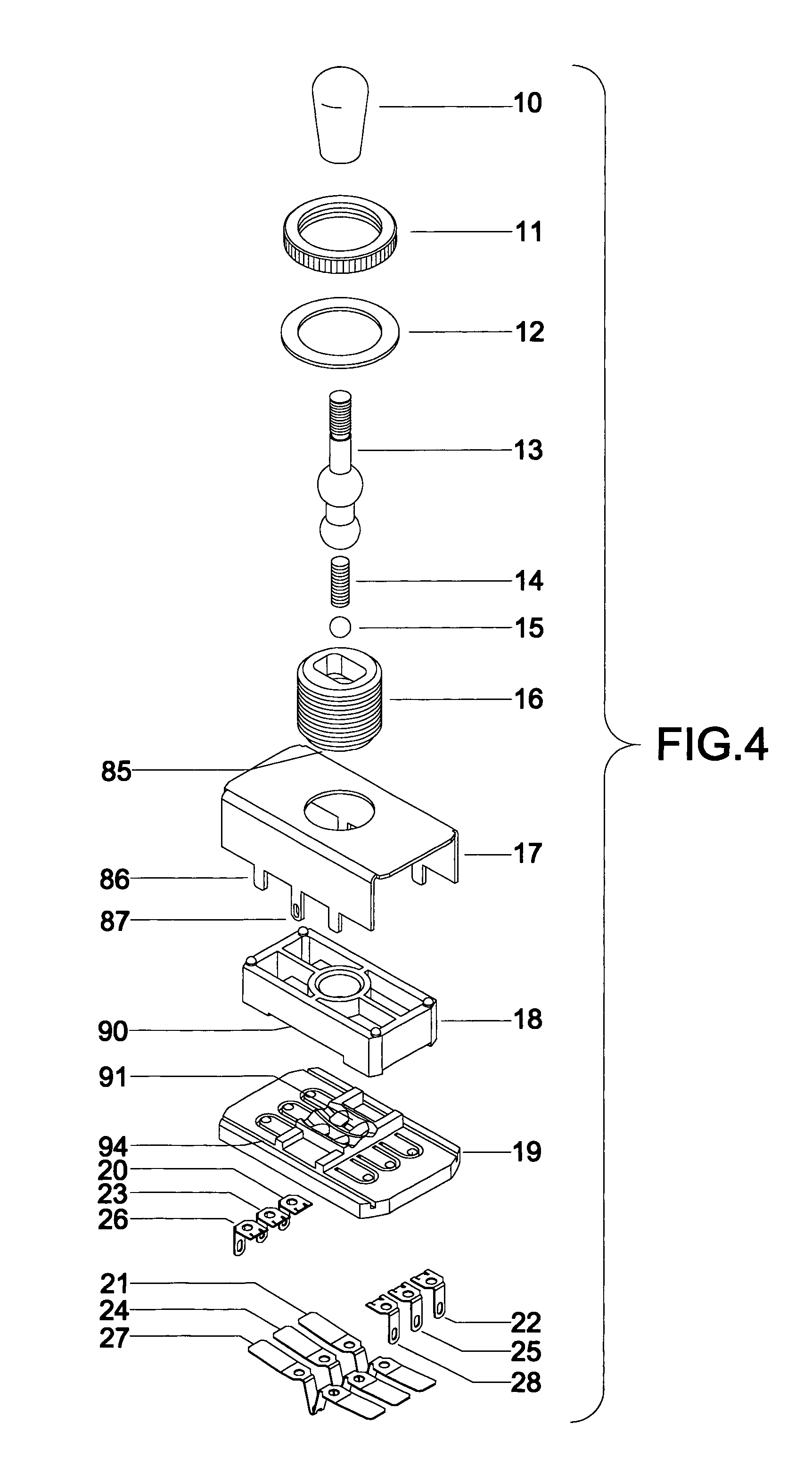
[0040]Compound selector switches may exist in a variety of forms and two main embodiments are described herein. Embodiment ‘A’ manifests a compound version of a typical three-position selector switch and is illustrated and described in FIG. 1 through FIG. 11. Embodiment ‘B’ manifests a compound version of a typical five-position selector switch and is illustrated and described in FIG. 12 through FIG. 24.

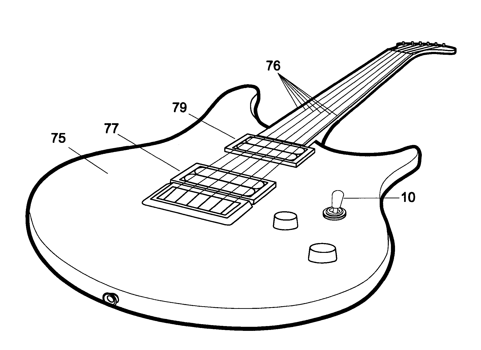
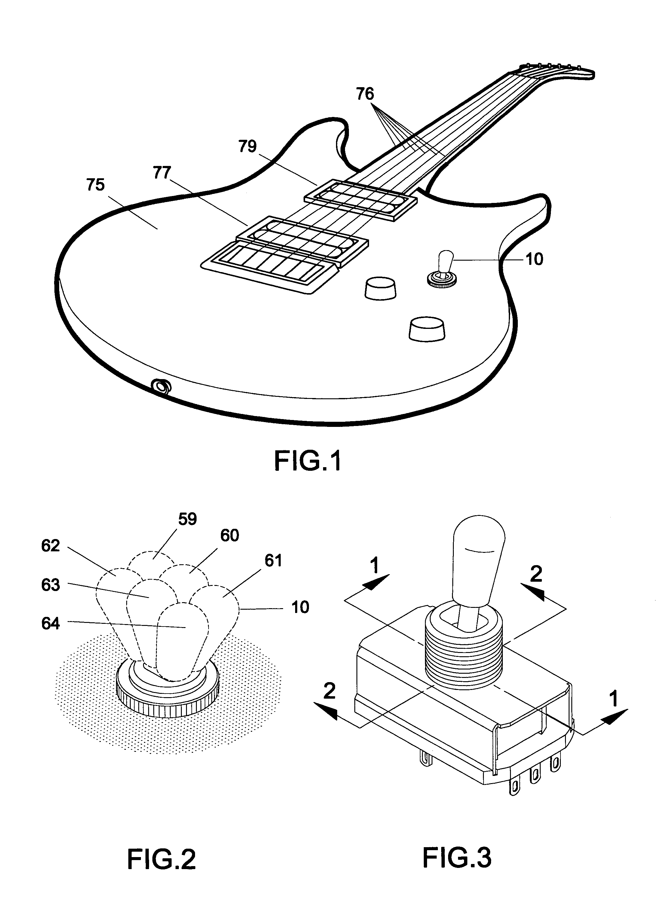
[0041]In respect of embodiment ‘A’, FIG. 1 illustrates a stringed instrument of the electric guitar type wherein a plurality of strings 76 are anchored and tensioned in such a way that their vibration interacts with bridge pickup 77 and neck pickup 79 which are also mounted on guitar body 75. Mounted internally within the guitar but with outwardly protruding toggle member 10, the compound selector switch is positioned so as to be manually operable by the player.

[0042]FIG. 2 shows an enlarged view of said outwardly protruding toggle member 10 and illustrates the various index position...


PUM


Abstract

A selector switch for musical instruments, such as electric guitars. is provided having a single, manually operated toggle member adapted to perform greater functionality. A selector switch is disclosed which indexes longitudinally for the electrical connection of pickup(s) for resultant amplification but will additionally provide further associated connectivity by means of a transverse indexing motion thus availing expanded switching function from a single switch apparatus. This inventive step is referred to as a compound selector switch.

Description

CROSS-REFERENCE TO OTHER RELATED APPLICATIONS[0001]This application relates to and claims priority from GB Patent Application Number GB 0325103, filed on Oct. 28, 2003, disclosure of which is incorporated herein by reference.BACKGROUND OF THE INVENTION[0002]1. Field of the Invention[0003]This invention relates to pickup switching apparatus for electric guitars, of any type, having more than one pickup. Electric guitar players prefer to selectively use: pickup(s); pickup configuration; additional electrical circuitry and types of amplification in different combinations so as to produce those tonal qualities suitable to the varying playing styles which they favour. Changing between such tonalities may be a frequent requirement and can involve multiple switch operation.[0004]On a two pickup guitar, a conventional three-position toggle switch is the primary means of selection and will connect either pickup alone at it's extreme index positions, or both pickups in parallel in it's centra...

Claims


Application Information

Patent Timeline
Patent Type & Authority Patents(United States)
IPC IPC(8): G10H1/18G10H3/12G10H3/18H01H25/00
CPCG10H3/182H01H25/00G10H2220/515G10H3/18H01H25/006
Inventor BRYCE, ALASDAIR JAMES
Owner BRYCE ALASDAIR JAMES
Learn More