Computer communication providing quality of service

Inactive Publication Date: 2007-04-24
BRITISH TELECOMM PLC
View PDF19 Cites 137 Cited by
  • Summary
  • Abstract
  • Description
  • Claims
  • Application Information

AI Technical Summary

Benefits of technology

[0012](ii) the client computer receiving data from the server computer via the second buffer element of the network node in response to the transmission of a first control signal from the client computer to the server computer. Additionally, the method may consist of the additional step of
[0013]The first control signal may be generated by the client computer in response to the level of data stored in a client computer data cache attaining a first, upper threshold value. The second control signal may be generated by the client computer in response to the level of data stored in a client computer data cache attaining a second threshold value which is lower then the first threshold value. Additionally, the communications route between the server computer and the client computer may comprise more than one network node and the selection of either the first or the second buffer elements in response to a control signal occurs within one or more of the network nodes which comprise the communications route between the server computer and the client computer. A data carrier may contai

Problems solved by technology

The increase in the use of multimedia communications over computer networks, for example audio and video streaming, television multicasting and broadcasting, etc. will also increase the difficulty involved in supplying these services with an acceptable QoS to all users due to the high bandwidths required and the real-time nature of the data.
While it may be possible to meet the desired QoS targets by increasing network capacity, i.e. increasing the capacity of transmission links and increasing the throughputs of switches and routers, this will necessitate significant capital expenditure and this investment may make the costs of the supplied services prohibitively high.
The drawback of establishi

Method used


Image

  • Computer communication providing quality of service
  • Computer communication providing quality of service
  • Computer communication providing quality of service

Examples


Embodiment Construction

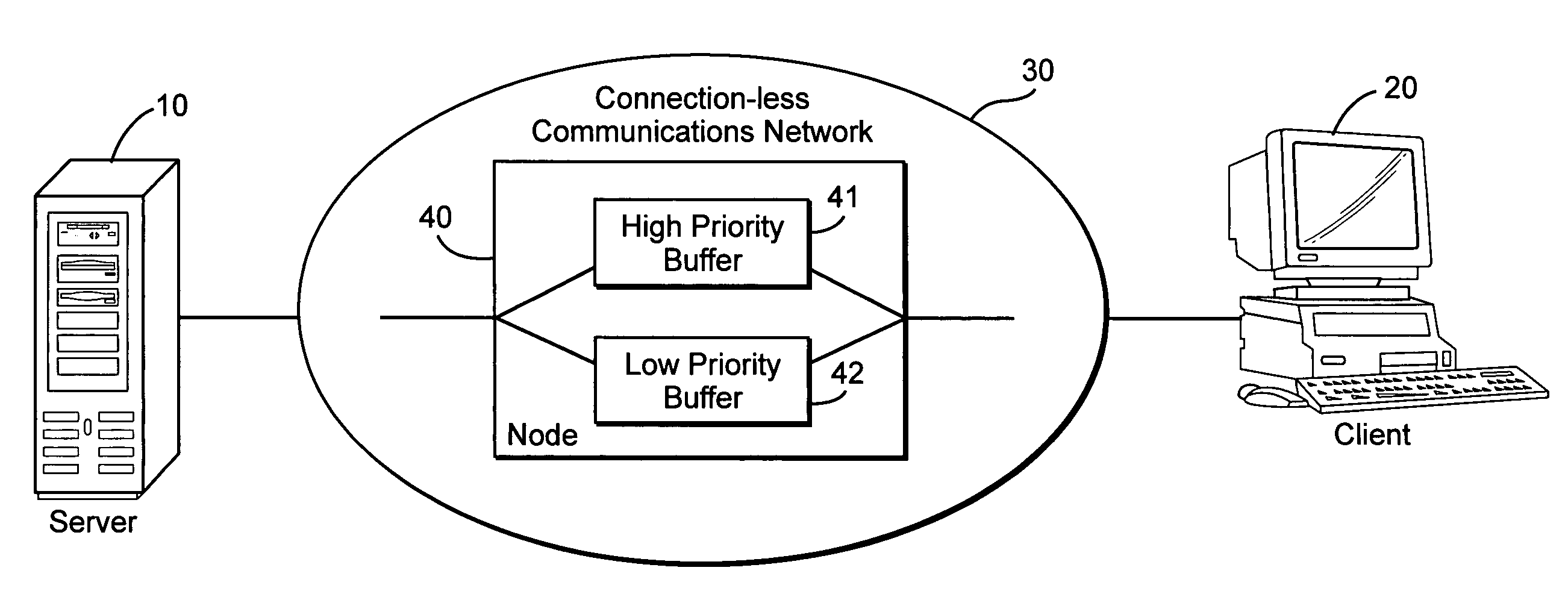
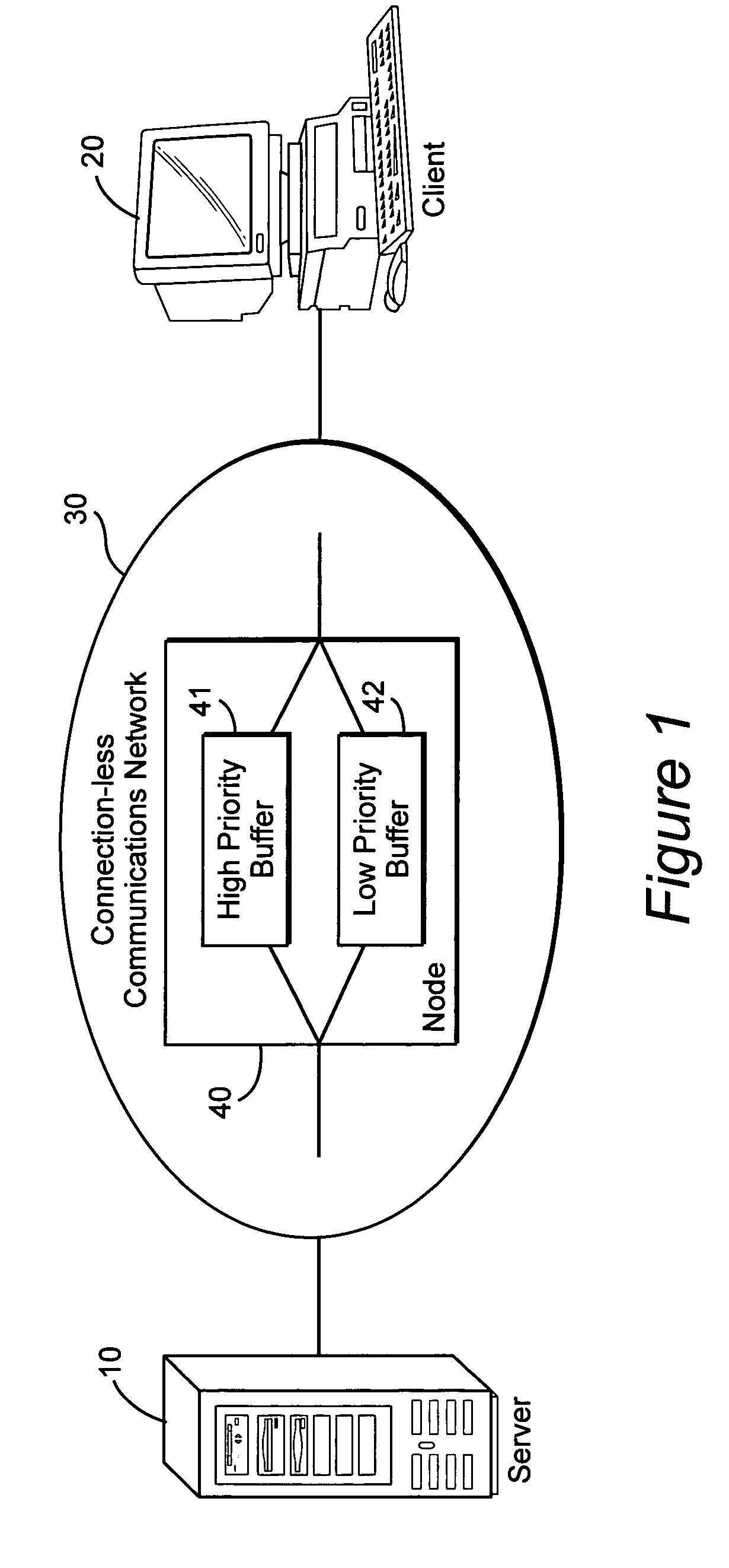
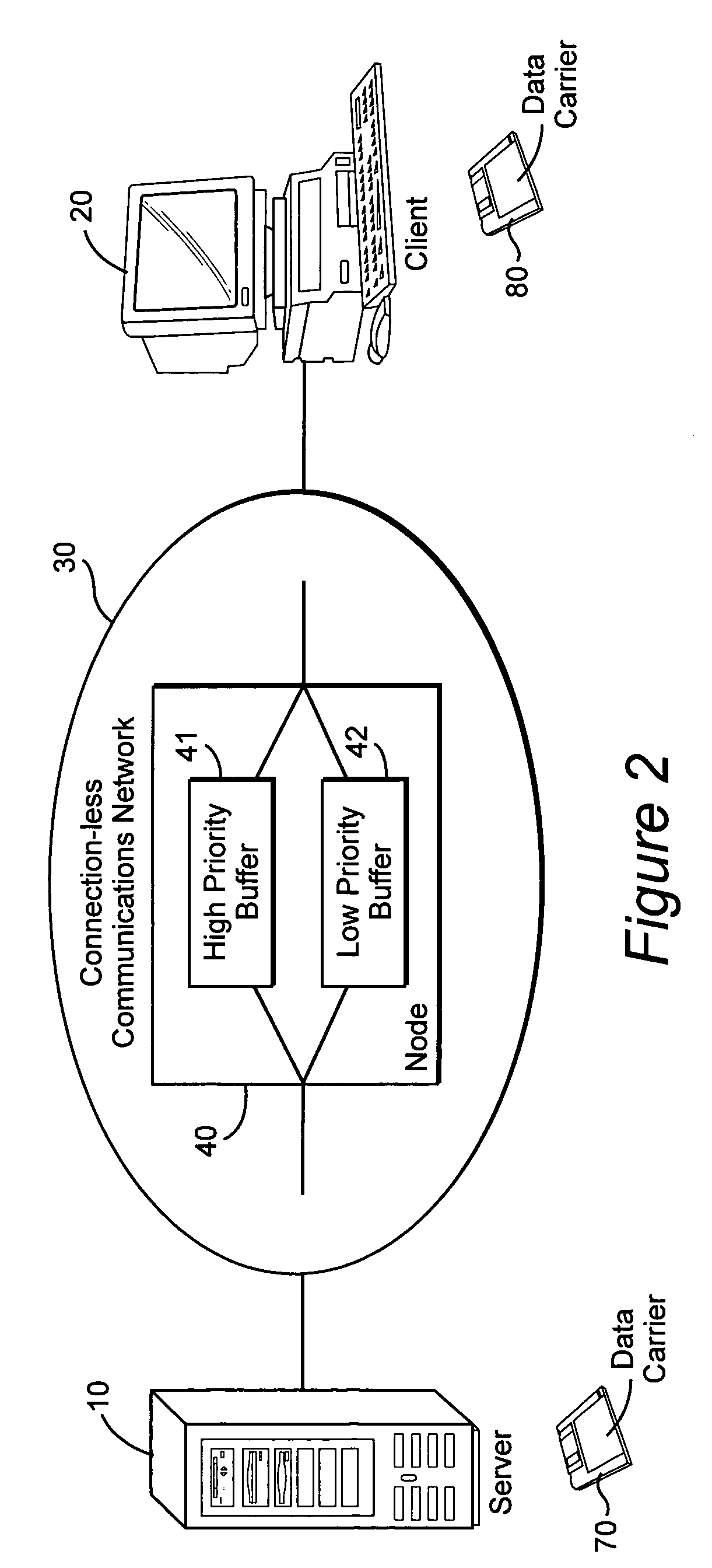
[0019]FIG. 1 shows a schematic depiction of a communications network over which a method of communication according to the invention may be used. Server computer 10 is connected to client computer 20 via a connection-less communications network 30, which includes at least one network node 40 in the communication route between the server computer 10 and the client computer 20. Each network node comprises two buffer elements 41&42, into which arriving packets are sorted on arrival at each network node. A flag in the header of each data packet determines which buffer element the packet is switched into. One of the buffer elements 41 is designated as a high priority buffer whilst the other buffer element 42 is designated as a low priority buffer. The high priority buffer 41 has preferential access to the output of the network node such that a majority of the bandwidth used by the network node is reserved for the high priority buffer. The remainder of the output bandwidth of the network ...


PUM


Abstract

A method is provided for more efficiently transmitting data from a server computer to a client computer over a communications network, the nodes of which are capable of providing two classes of transmission quality. Data is transmitted using the high priority class until a local cache at the client computer is filled to a certain upper threshold, at which point the data is transmitted using the low priority class. If the local cache at the client computer subsequently reaches a lower threshold then the transmitted reverts to the use of the high priority class. The communications network may be connection-based (e.g. ATM) or connection-less (e.g. the Internet).

Description

BACKGROUND OF THE INVENTION[0001]1. Field of the Invention[0002]This invention relates to a method of communicating data from a server computer to a client computer.[0003]2. Related Art[0004]The Quality of Service (QoS) provided by operators of communications networks and systems is very important, especially in sectors for which a reliable, high-speed supply of information is required e.g. banking, share dealing, etc. The increase in the use of multimedia communications over computer networks, for example audio and video streaming, television multicasting and broadcasting, etc. will also increase the difficulty involved in supplying these services with an acceptable QoS to all users due to the high bandwidths required and the real-time nature of the data. While it may be possible to meet the desired QoS targets by increasing network capacity, i.e. increasing the capacity of transmission links and increasing the throughputs of switches and routers, this will necessitate significant ...

Claims


Application Information

Patent Timeline
IPC IPC(8): G06F11/00G06F15/173H04L12/56H04L12/70H04L12/801H04L12/851H04L12/861H04L29/06H04Q11/04
CPCH04L29/06H04L47/10H04L47/2433H04L47/29H04L49/90H04Q11/0478H04L2012/5634H04L2012/5651H04L2012/5682H04L67/42H04L9/40H04L67/02H04L67/01
Inventor HODGKINSON, TERENCE GCHERRADI, YOUNES
Owner BRITISH TELECOMM PLC
Why Eureka
Try Eureka