Lightweight bumper for automobiles

Active Publication Date: 2007-05-01
FORD GLOBAL TECH LLC
View PDF8 Cites 28 Cited by
  • Summary
  • Abstract
  • Description
  • Claims
  • Application Information

AI Technical Summary

Benefits of technology

[0026]FIG. 6 is a graph representing the displacement of the bumper beam section as a function of the force required to effect the deformation under low speed (5 mph) conditions, the bumper beam incorporating the principles of the instant invention being plotted in solid lines while a benchmark bumper beam is plotted in phantom lines;
[0027]FIG. 7 is a graph representing the displacement of the bumper beam section as a function of the energy absorbed to effect the deformation under low speed (5 mph) conditions, the bumper beam incorporating the principles of the instant invention being plotted in solid lines while a benchmark bumper beam is plotted in phantom lines;
[002

Problems solved by technology

The hollow central section includes a groove of varying depths to define the “B” configuration;

Method used


Image

  • Lightweight bumper for automobiles
  • Lightweight bumper for automobiles
  • Lightweight bumper for automobiles

Examples


Embodiment Construction

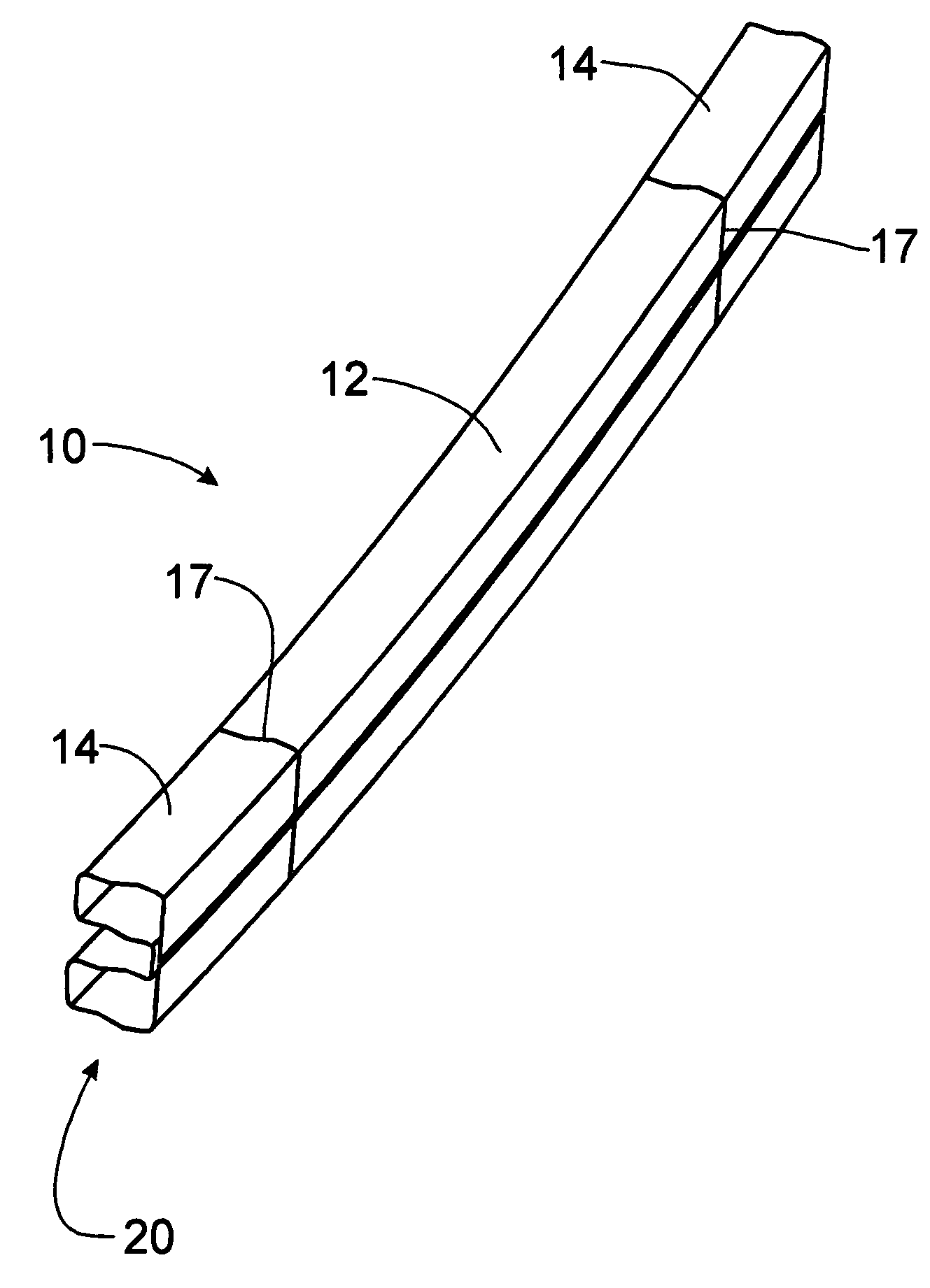
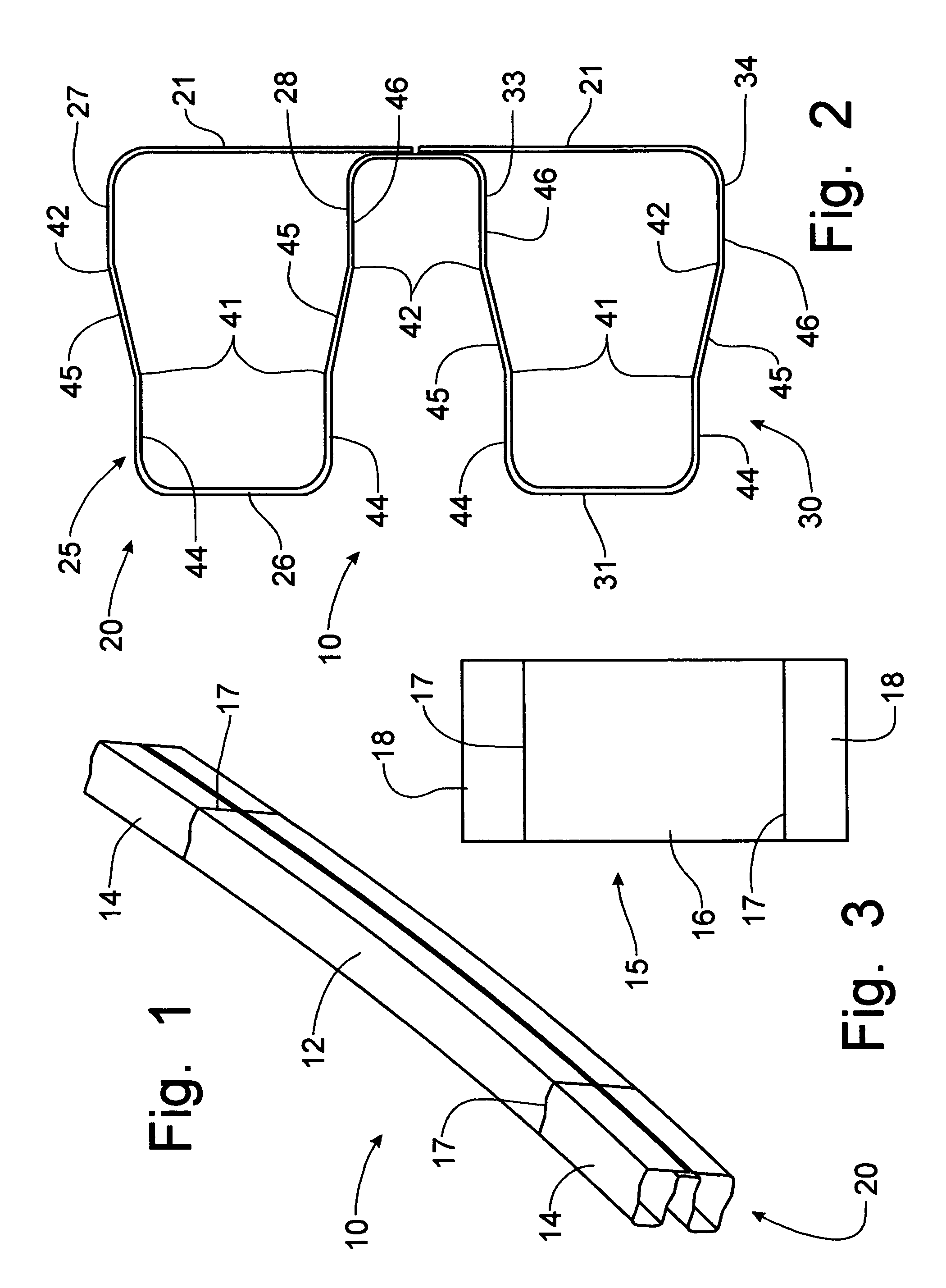
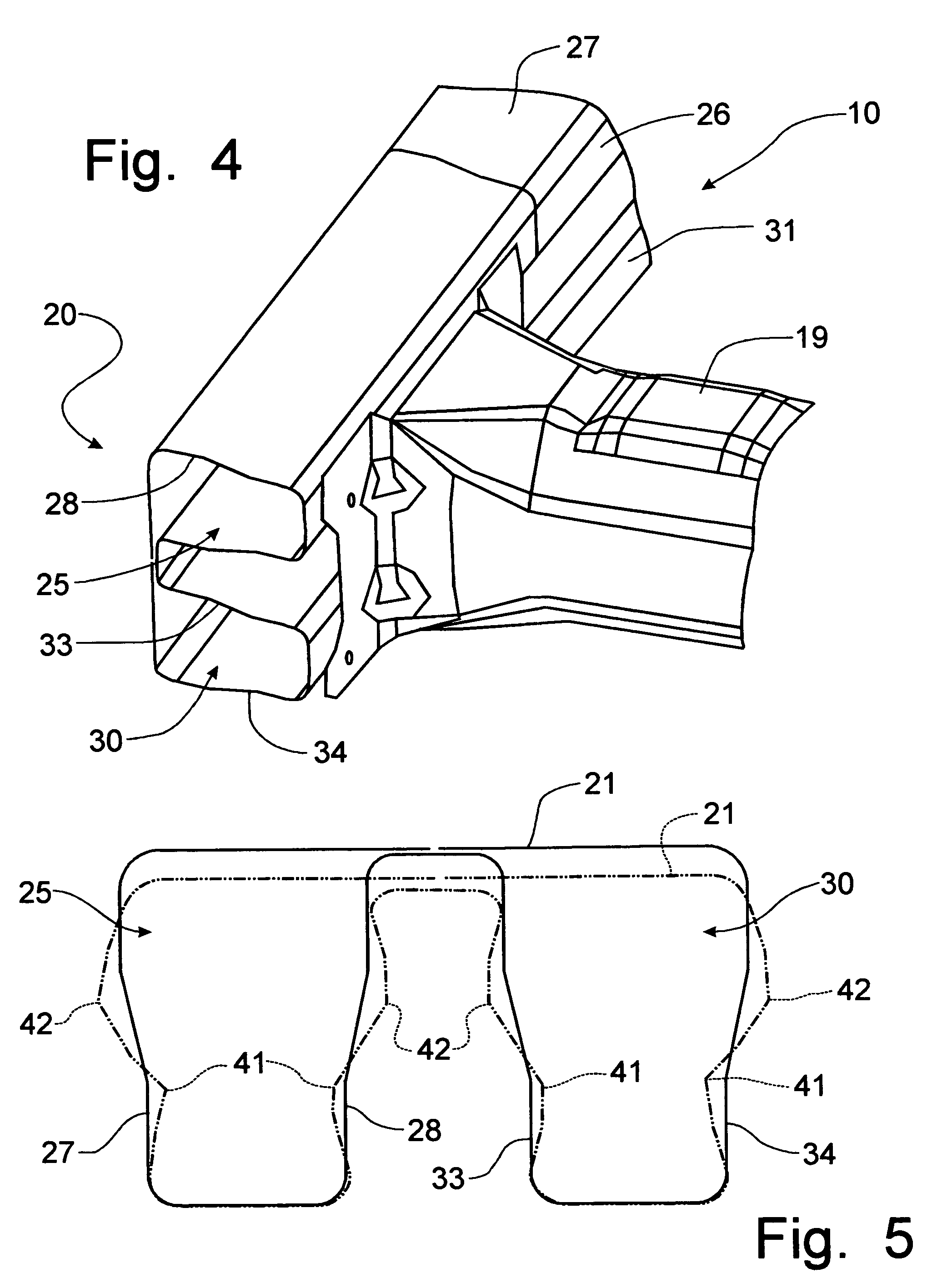
[0030]Referring to FIGS. 1–4, a bumper beam formed according to the principles of the instant invention, to be mounted on the lower frame rails at a forward location of an automobile frame, can best be seen.

[0031]The bumper beam 10 is formed from a tailor welded blank 15, depicted in FIG. 3, with a 0.7 mm gage central piece of sheet metal 16 and with 1.3 mm gage sheet metal pieces 18 laser welded to the opposing lateral edges 17 of the central piece 16 to provide a single sheet metal blank 15 from which the bumper beam 10 is to be formed. The central piece of sheet metal 16 corresponds to the center portion 12 of the bumper beam 10, while the side pieces 18 of the blank 15 correspond to the respective terminal ends 14 of the bumper beam where the lower frame rails 19 are affixed, as is depicted in FIG. 4. Preferably, the central and side pieces 16, 18 of the tailor welded blank 15 are constructed from ultra high strength steel commonly referred to as M220 Martinsite steel.

[0032]The ...


PUM


Abstract

A bumper beam is formed from a tailor welded blank with thinner gage sheet metal laser welded to thicker gage sheet metal at opposing sides thereof. The tailor welded blank is then formed into a bumper beam having a uniform B-shaped cross-sectional configuration from one terminal end to the other. The heavier gage material in the tailor welded blank corresponds to the terminal ends of the bumper beam where the bumper beam is affixed to the lower frame rails of the vehicle chassis thus placing the greater energy absorption qualities for the bumper beam only at the locations in which they are needed without requiring reinforcement inserts.

Description

FIELD OF THE INVENTION[0001]This invention relates to a bumper for an automotive vehicle and, more particularly, to a lightweight bumper that provides crash performance equivalent to conventional bumper configurations.BACKGROUND OF THE INVENTION[0002]Bumpers are mounted at the forward extremity of a vehicle to protect the chassis of the vehicle from minor impacts. The bumper is mounted to the lower frame rails of the vehicle chassis for support thereof and functions to withstand minor impacts by collapsing to absorb the energy encountered through the impact.[0003]The structure of a bumper can be formed in a “B-shaped” configuration with a front face flange and upper and lower cells. This B-shaped structural configuration can be seen in U.S. Pat. No. 6,042,163, issued to Raymond Reiffer on Mar. 28, 2000. The Reiffer patent discloses a bumper having a primary central member shaped in the “B” configuration with end pieces welded to the primary central member after formation to provide ...

Claims


Application Information

Patent Timeline
IPC IPC(8): B60R19/18
CPCB60R19/18B60R2019/1826
Inventor BACCOUCHE, RIDHAMAHMOOD, HIKMATMADASAMY, CHELLIAHWAGNER, DAVID
Owner FORD GLOBAL TECH LLC
Why Eureka
Try Eureka