Vehicle bumper beam mounting structure

a technology for mounting structures and bumper beams, which is applied to bumpers, vehicle components, vehicular safety arrangments, etc., can solve the problems that cannot be expected to positively absorb impact from bumper beams, and achieve the effect of preventing deformation of vehicle body parts

Inactive Publication Date: 2007-05-01
HONDA MOTOR CO LTD
View PDF7 Cites 33 Cited by
  • Summary
  • Abstract
  • Description
  • Claims
  • Application Information

AI Technical Summary

Benefits of technology

[0011]Accordingly, in a vehicle minor collision, the mounting members and / or the bumper beam deform, absorbing the impact, and thus preventing deformation of the vehicle body members and the like.
[0012]The curved portions each preferably have a weak portion for allowing deformation of the bumper beam. The curved portions thus absorb the impact of a minor collision, preventing deformation of the vehicle body members and the like.

Problems solved by technology

Therefore, it cannot also be expected to positively absorb an impact by the bumper beam 321 in a minor collision.

Method used


Image

  • Vehicle bumper beam mounting structure
  • Vehicle bumper beam mounting structure
  • Vehicle bumper beam mounting structure

Examples


Embodiment Construction

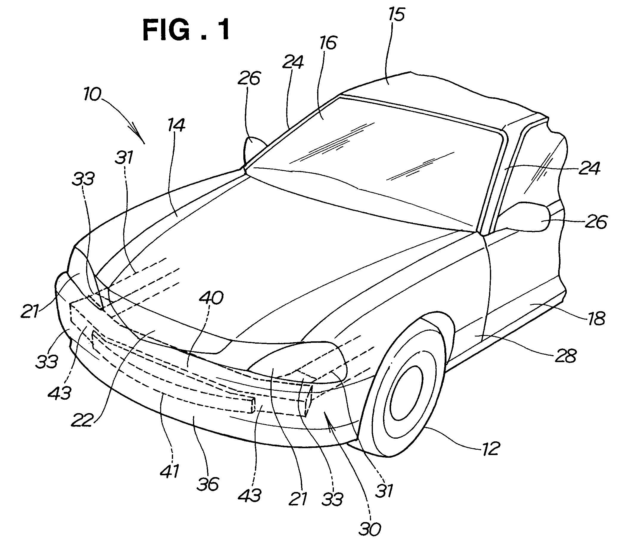
[0026]FIG. 1 shows a vehicle employing a bumper beam mounting structure according to the present invention. In the figure, reference numeral 10 denotes a vehicle; 12, a front wheel; 14, a bonnet; 15, a roof; 16, a windshield; 18, a front door; 21, a headlight; 22, a front grille; 24, a front pillar; 26, a door mirror; 28, a front fender; 31, a front side member (vehicle body member); 36, a bumper face (front bumper face); 40, a bumper beam; and 41, an impact absorber.

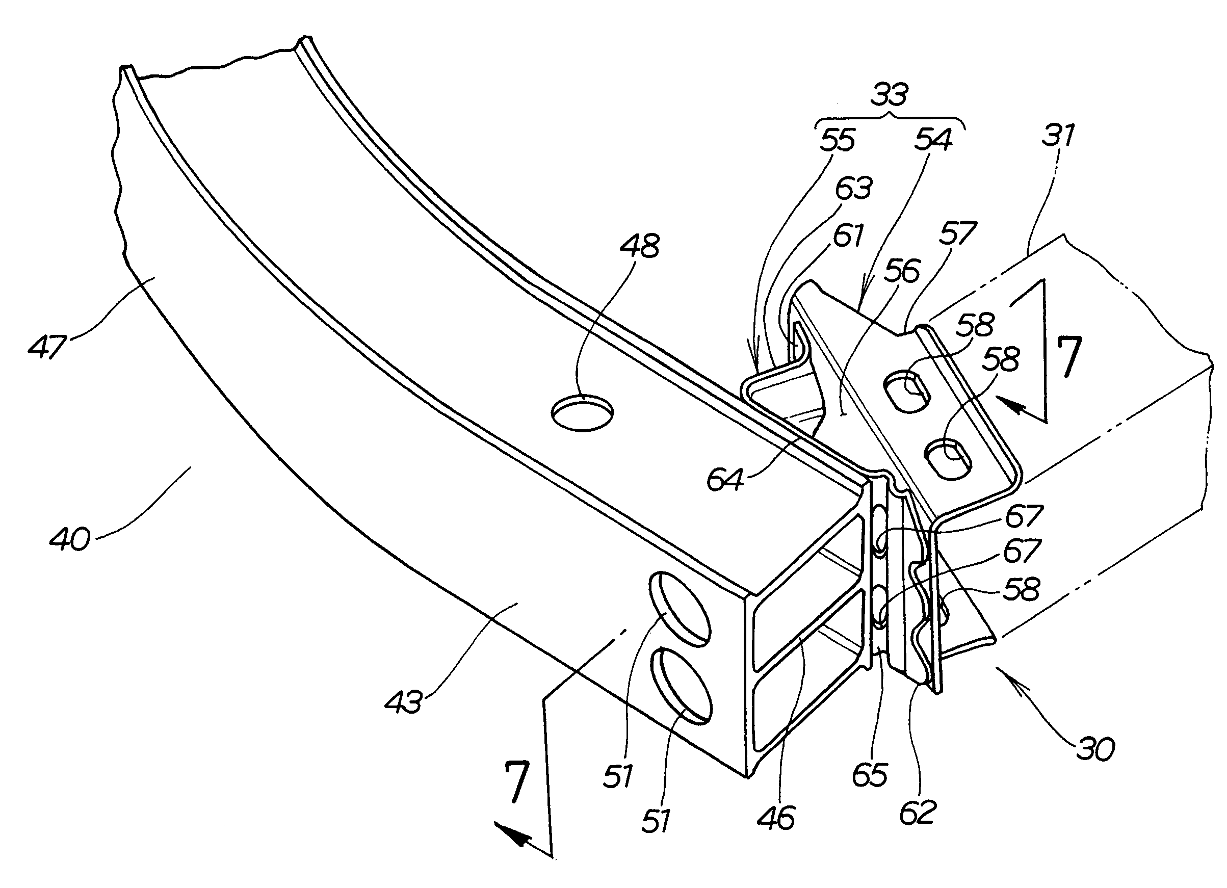
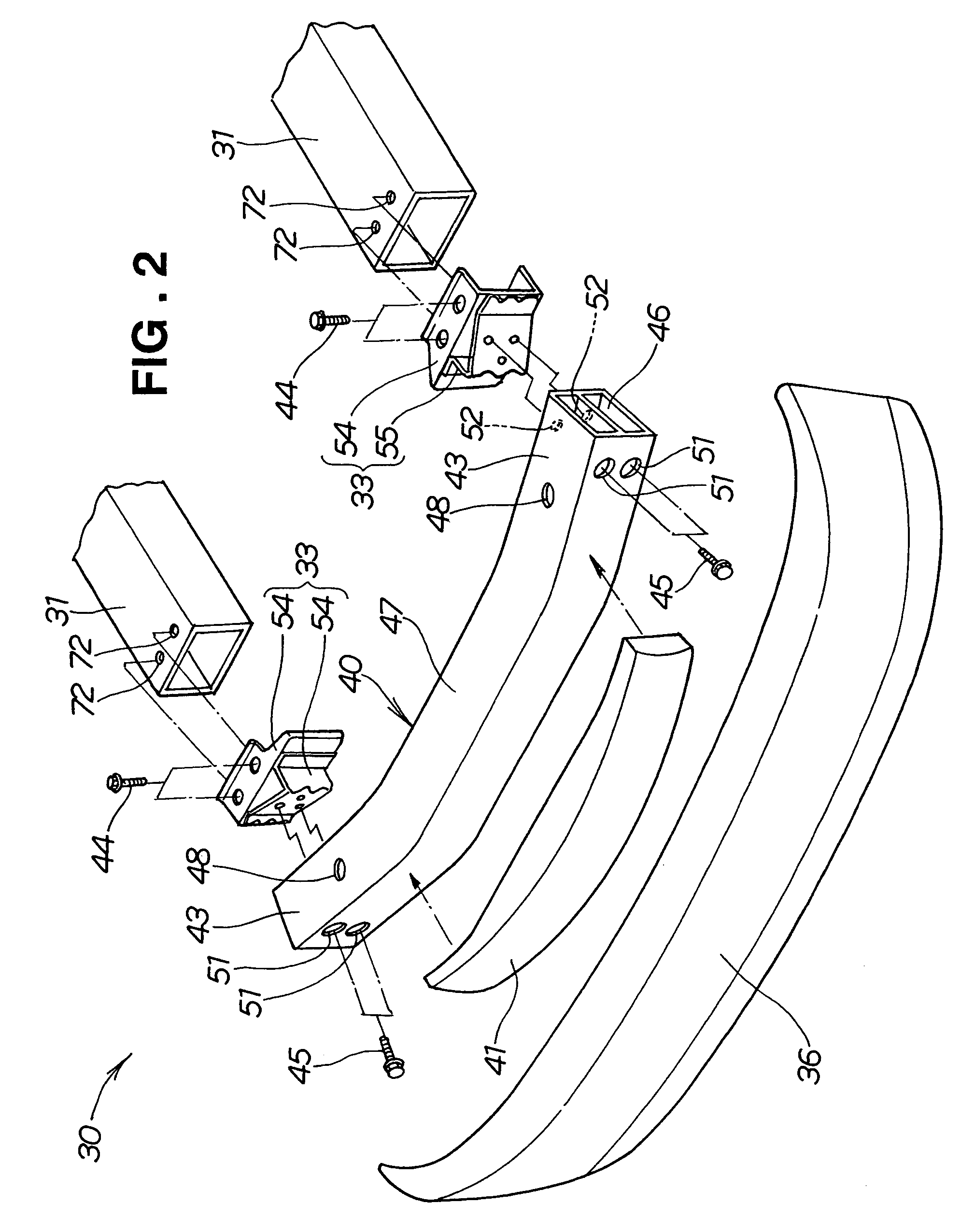
[0027]A bumper beam mounting structure 30 includes the bumper beam 40 formed from an aluminum extrusion. The bumper beam 40 has opposite end portions curved rearward of the vehicle body, forming right and left curved portions 43, 43. Right and left mounting members 33, 33 are attached to the right and left curved portions 43, 43, respectively. The mounting members 33, 33 are attached to the front side members 31, 31, so that an impact applied from the bumper beam 40 to the vehicle body is substantially absorbed by the m...


PUM


Abstract

A bumper beam mounting structure for absorbing an impact at a bumper beam and mounting members thereof in a vehicle minor collision is provided. The mounting structure has the mounting members attached to curved portions of right and left curved ends of the bumper beam. The mounting members are attachable to vehicle body members. The mounting members are in a right triangular shape in a plan view. A sloping portion corresponding to the hypotenuse is formed with a depressed portion for absorbing an impact.

Description

FIELD OF THE INVENTION[0001]The present invention relates to a vehicle bumper beam mounting structure which allows a bumper beam itself or mounting portions of the bumper beam to absorb a small impact applied to a vehicle body.BACKGROUND OF THE INVENTION[0002]Bumper beams configured to absorb an impact by the bumper beams themselves or mounting portions of the bumper beams in a minor collision (when a small impact is applied to a vehicle body) have been in practical use. This kind of bumper beam only needs to be set small in rigidity at the bumper beam or at mounting portions of the bumper beam for practical use.[0003]Japanese Patent Laid-Open Publication No. HEI-7-265988 discloses a bumper beam mounting structure in which mounting members are attached to a bumper beam, and the mounting members are attached to a vehicle body. This bumper beam mounting structure will be described with reference to FIGS. 10 and 11.[0004]A conventional bumper beam mounting structure 320 shown in FIG. 1...

Claims


Application Information

Patent Timeline
Patent Type & Authority Patents(United States)
IPC IPC(8): B60R19/34
CPCB60R19/18B60R19/34B60R2019/182B60R2019/186
Inventor HONDA, KEIICHIOMURA, KAZUOSUZUKI, TOSHIHIKO
Owner HONDA MOTOR CO LTD
Why Eureka
Try Eureka