Press-fit fixing terminal, and electronic component having the same terminal

a technology of fixing terminal and electronic component, which is applied in the direction of fixed connection, coupling device connection, securing/insulating coupling contact member, etc., can solve the problems of incurring additional cost and inviting deformation in the plating process, and achieve excellent contact stability and stable conta

Inactive Publication Date: 2007-05-01
PANASONIC CORP
View PDF6 Cites 16 Cited by
  • Summary
  • Abstract
  • Description
  • Claims
  • Application Information

AI Technical Summary

Benefits of technology

[0014]This construction allows the press-fit fixing terminal to be made of thin material in thickness, so that the terminal can be resistant to plastic deformation and stable in contact. On top of that, the surface of original material not have been cut can be used as a contacting face, so that electrical contact becomes stable. The material undergone a plating process can be used, so that an inexpensive press-fit fixing terminal excellent in contact stability is achievable, and an electronic component equipped with this press-fit fixing terminal is obtainable.

Problems solved by technology

The plating process incurs an additional cost and sometimes invites deformation.

Method used


Image

  • Press-fit fixing terminal, and electronic component having the same terminal
  • Press-fit fixing terminal, and electronic component having the same terminal
  • Press-fit fixing terminal, and electronic component having the same terminal

Examples


Embodiment Construction

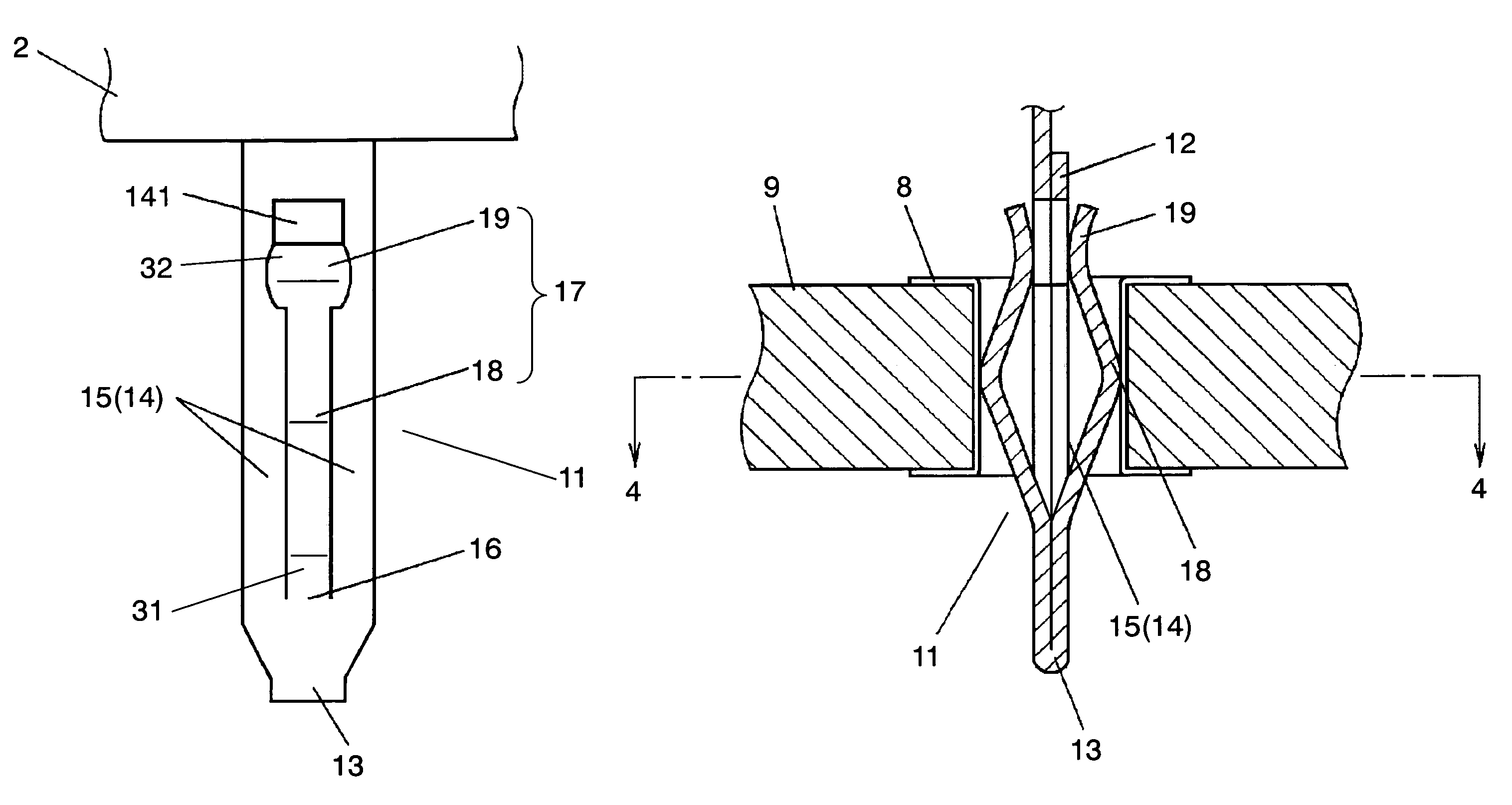
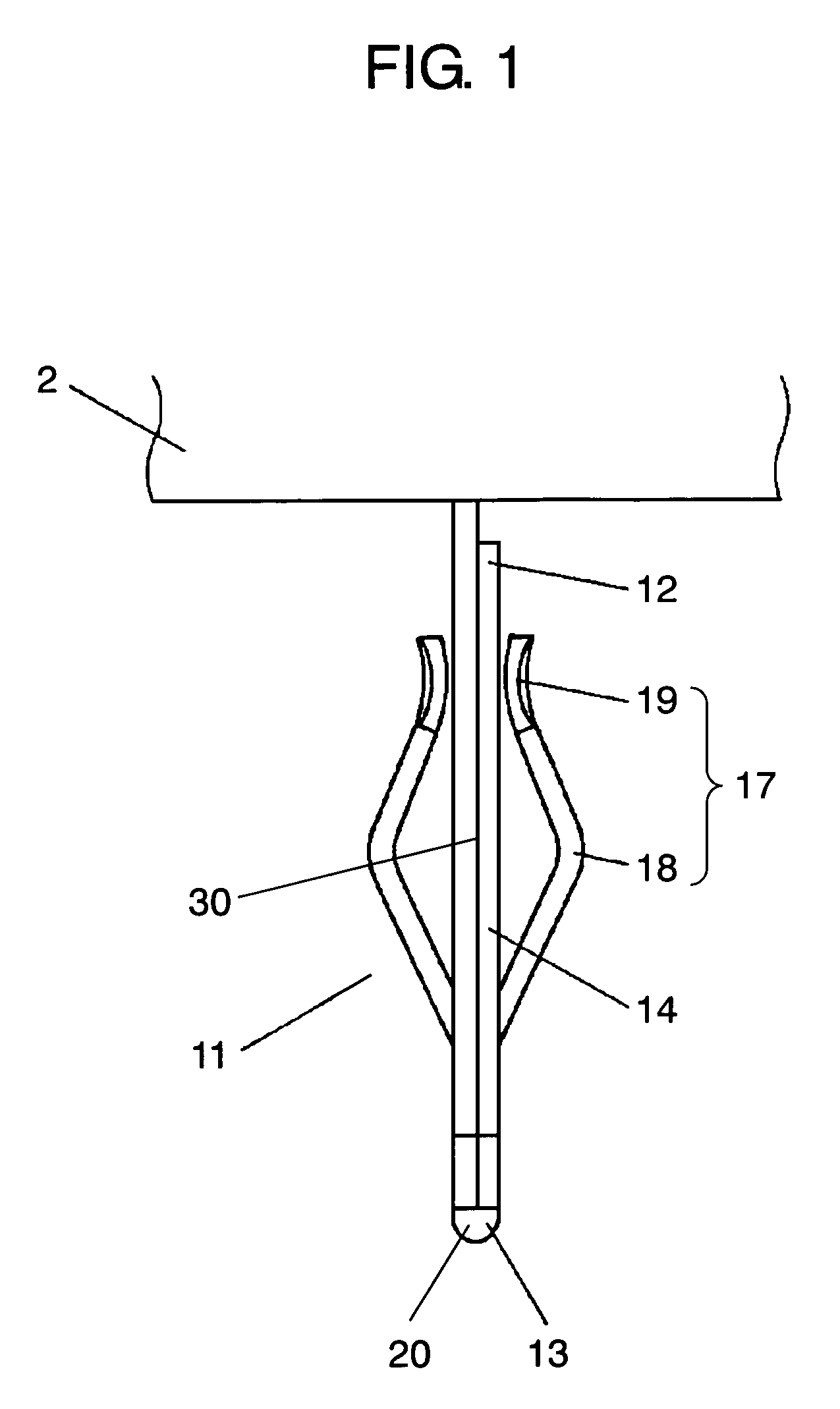
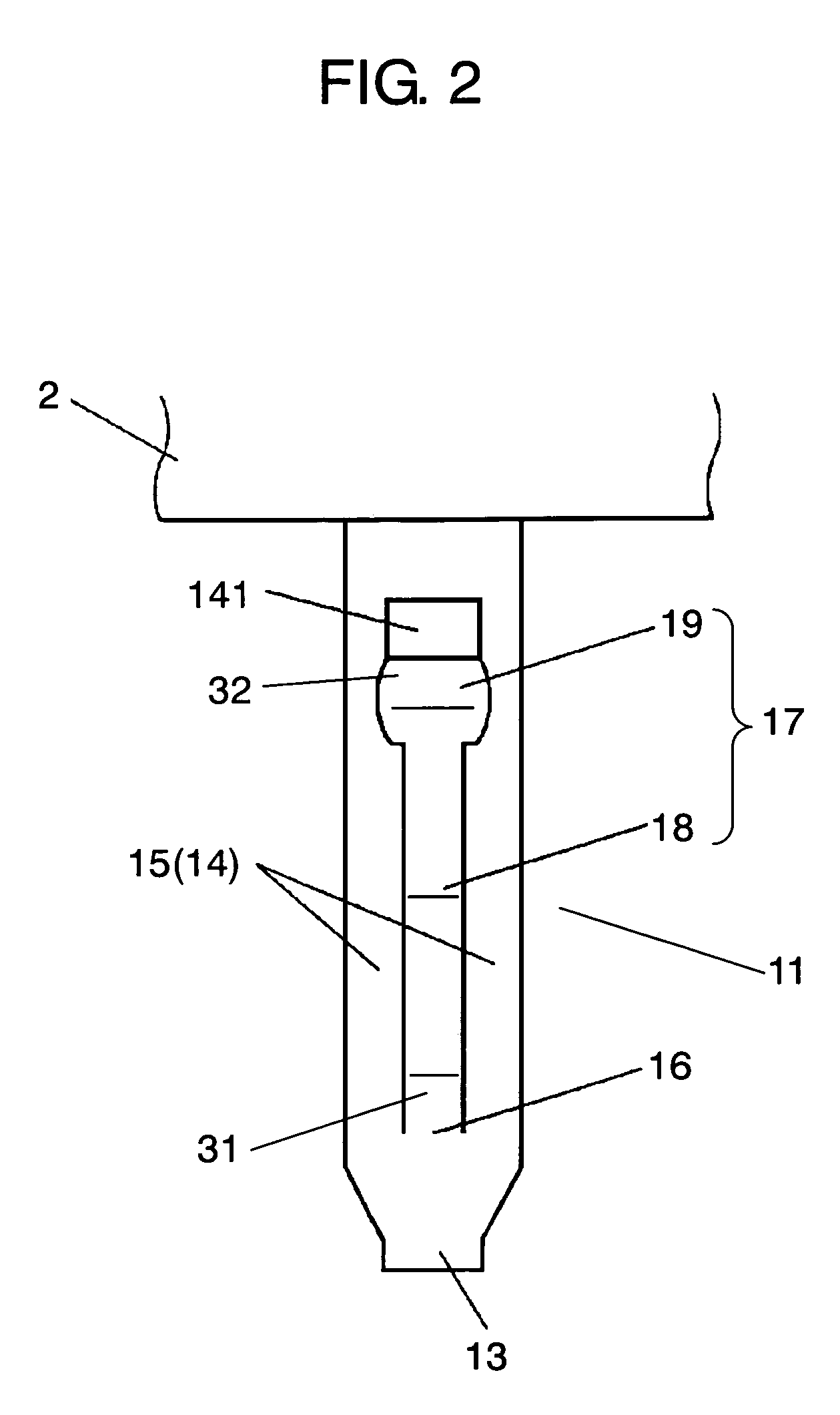
[0023]An exemplary embodiment of the present invention is demonstrated hereinafter with reference to the accompanying drawings. FIG. 1 shows a front view of a press-fit fixing terminal in accordance with the embodiment of the present invention. FIG. 2 shows a lateral view of the press-fit fixing terminal shown in FIG. 1. FIG. 3 shows vertical sectional view illustrating the press-fit fixing terminal, shown in FIG. 1, being press-fitted into a through-hole of a wiring board. FIG. 4 shows a horizontal sectional view taken along line 4—4 of FIG. 3.

[0024]In FIG. 1 and FIG. 2, press-fit fixing terminal 11 of the present invention is mountable to a wiring board by being press-fitted into a through-hole of the wiring board, and terminal 11 includes flat plate section 14 and resilient contacting section 17.

[0025]Flat plate section 14 is made of metal thin plate and double-backed, so that end 12 is placed near the root, and bent point 20 works as insertion tip 13 when terminal 11 is press-fi...


PUM


Abstract

A press-fit fixing terminal is mountable to a wiring board by being inserted into a through-hole of the wiring board, and includes a flat plate section and a resilient contacting section. The flat plate section is made of metal thin plate and double-backed such that an end of the flat plate section is placed on a root side and a bent point works as an insertion tip when the terminal is inserted into the through-hole. The resilient contacting sections sandwich the double-backed portion of the flat plate section such that they are placed symmetrically with respect to the double-backed portion and both of the ridges of the resilient contacting section face outward viewed from the double-backed portion, so that each one of the resilient contacting sections forms a V-shape including an obtuse angle.

Description

FIELD OF THE INVENTION[0001]The present invention relates to a press-fit fixing terminal to be inserted into a through-hole of a wiring board in order to mount various electronic components to the wiring board, and the press-fit fixing terminal connects the component mechanically and electrically to the wiring board. The present invention also relates to electronic components having the same terminals.BACKGROUND OF THE INVENTION[0002]Methods of mounting electronic components onto a wiring board have focused on streamlining the mounting jobs, and also on alleviating the environmental load as a lead-free soldering. Under such a climate, a press-fit fixing terminal is employed to some mounting methods instead of soldering.[0003]This conventional press-fit fixing terminal is described with reference to FIG. 6–FIG. 8. FIG. 6 shows a front view of the conventional terminal, and FIG. 7 shows a lateral view of the terminal shown in FIG. 6. FIG. 8 shows a schematic sectional view cut along l...

Claims


Application Information

Patent Timeline
Patent Type & Authority Patents(United States)
IPC IPC(8): H01R13/42H01R12/55H01R12/58
CPCH01R12/585H05K3/308H05K2201/1059H05K2201/10765H05K2201/10856
Inventor HASHIMOTO, YUKIOMIURA, SEIKINISHIMOTO, TAKUMITOMAGO, TAKASHI
Owner PANASONIC CORP
Why Eureka
Try Eureka