Method and apparatus for signal power loss reduction in RF communication systems

a communication system and signal power loss technology, applied in the field of signal power loss reduction in communications systems, can solve the problems of diversity/multi-antenna systems, degrade the performance of pa and lna when measured from the antenna port, and achieve the effects of reducing losses, redundancy at the front end of an rf device, and reducing losses

Inactive Publication Date: 2007-05-01
THE CONNECTIVITY PATENT TRUST
View PDF20 Cites 124 Cited by
  • Summary
  • Abstract
  • Description
  • Claims
  • Application Information

AI Technical Summary

Benefits of technology

[0007]The present invention provides an architecture, method, and device wherein redundancies at the front end of an RF device can reduce losses that occur at the diversity switch. In highly integrated radio systems, silicon area is inexpensive and the cost of redundancy is low. The losses incurred by the diversity switches can be reduced by duplicating the number of PAs / LNAs as well as moving the antenna diversity switches from between the PA / LNA and antenna to after the PAs / LNAs.

Problems solved by technology

One problem recognized is the loss incurred through the diversity and transmit / receive switches.
The switches attenuate the RF signal and introduce noise, which degrades the performance of the PA and LNA when measured from the antenna port.

Method used


Image

  • Method and apparatus for signal power loss reduction in RF communication systems
  • Method and apparatus for signal power loss reduction in RF communication systems
  • Method and apparatus for signal power loss reduction in RF communication systems

Examples


Embodiment Construction

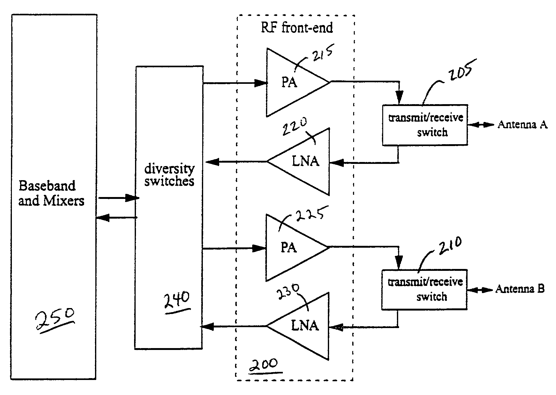
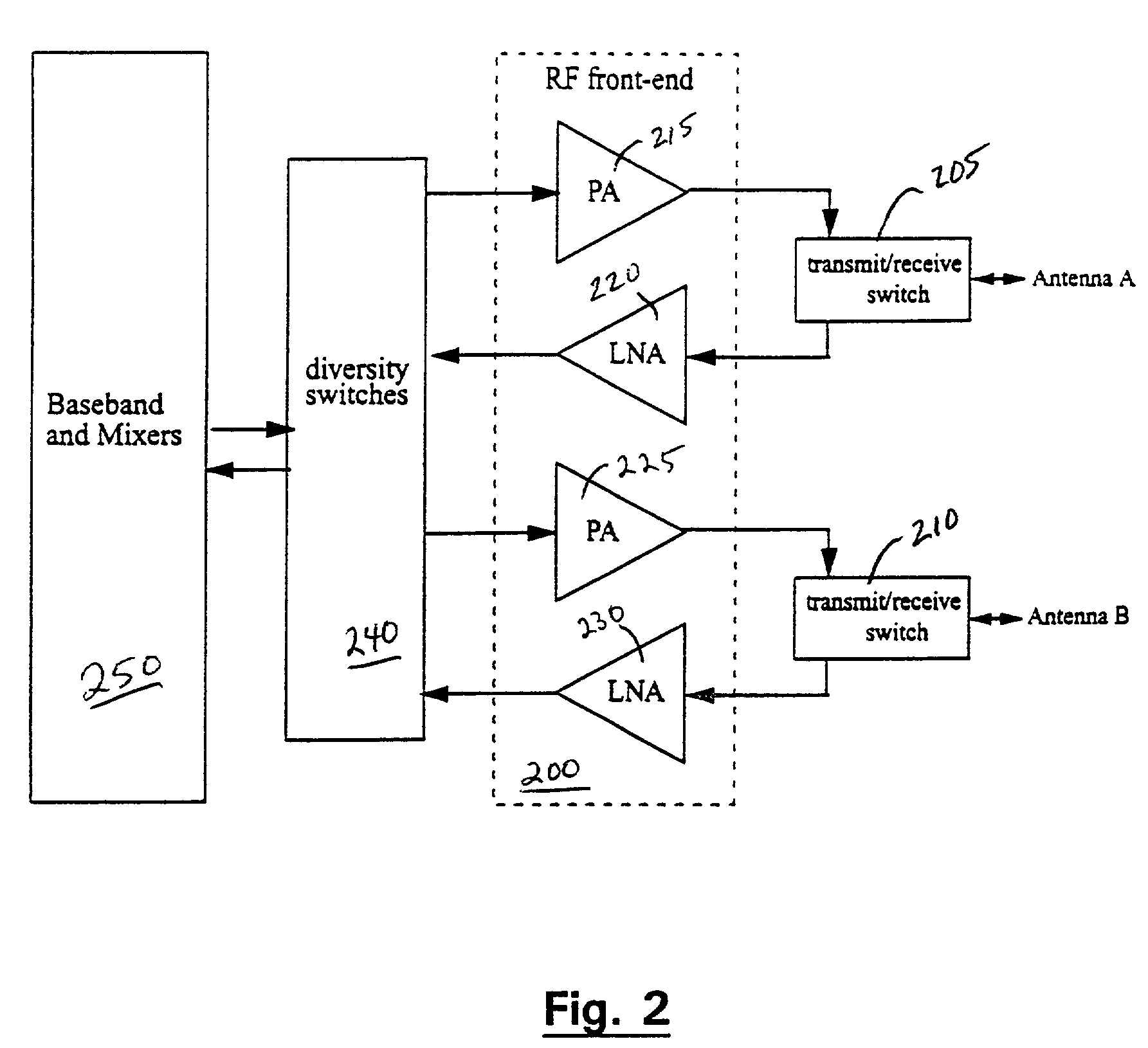
[0030]Referring again to the drawings, wherein like reference numerals designate identical or corresponding parts, and more particularly to FIG. 2 thereof, there is illustrated a block diagram of diversity antenna according to an embodiment of the present invention. The illustrated embodiment provides a framework from which signal losses incurred due to a diversity switch can be reduced.

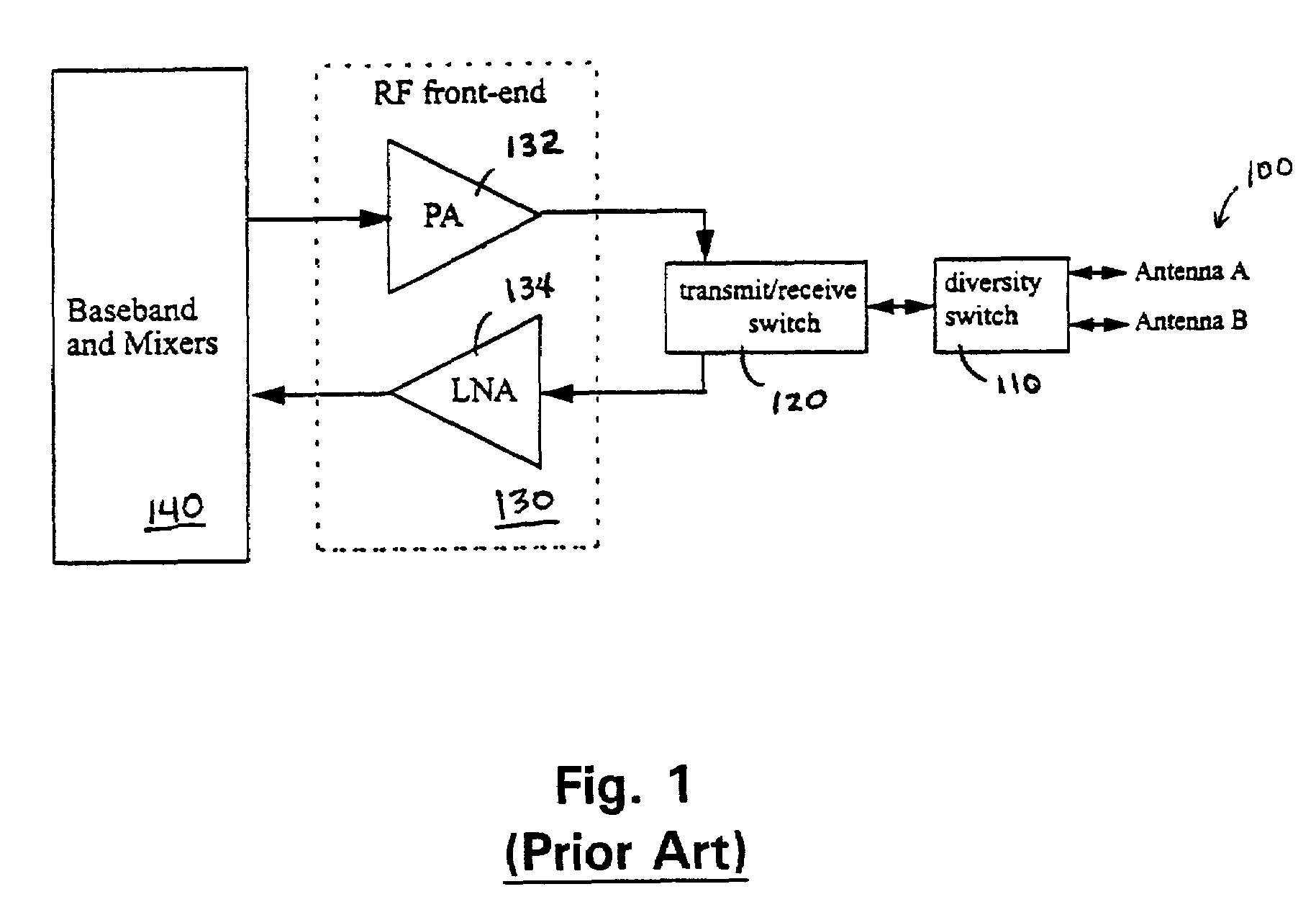
[0031]The signal affected most by inefficiencies, and therefore presenting the greatest design challenge is the signal as it is transmitted to and received from the antenna. The signal is received, for example, at antenna A, and is then directed, by transmit / receive switch 205, to the LNA 220. In the previous designs, a diversity switch was also included in the signal path from the antennas to the LNA. However, in the invention, RF front end 200 has an architecture that uses redundant front end components that eliminates the need for a diversity switch between the front end and the antennas.

[0032]In ...


PUM


Abstract

Multiple power amplifiers in an RF front end are coupled to multiple antennas without diversity switching between the PAs and antennas. Diversity switches direct signals to broadcast by a selected antenna to a PA coupled to the selected antenna. Multiple LNAs are similarly coupled to the diverse antennas. Having one PA and LNA set for each antenna removes the need for diversity switching between the PA / LNAs and each antenna improving signal reception. In one embodiment, a single external PA performs broadcast functions and plural on-chip LNAs are used for reception. In another embodiment, phase shifters are coupled to each PA and LNA, which provide beam forming capability for broadcasts, and in phase signal combinations for received signals.

Description

BACKGROUND OF THE INVENTION[0001]1. Field of Invention[0002]The present invention relates to reduction of signal power loss in communications systems. The invention is more particularly related to the reduction of signal power loss in wireless RF systems. In addition, the invention relates to implementing antenna diversity in wireless systems.[0003]2. Discussion of Background[0004]The use of multiple antennas has become a popular method of improving performance of wireless devices. A simple technique is called “switch diversity”, where a radio can alternatively transmit and receive through separate antennas, using only one antenna at a time. The radio can then decide which antenna to use based upon the success of previous communications. FIG. 1 is a diagram of a traditional “switch diversity” architecture. A pair of antennas, Antenna A and Antenna B (diversity antennas 100) are located at diverse physical locations and / or are antennas having diverse physical properties (gain, direct...

Claims


Application Information

Patent Timeline
Patent Type & Authority Patents(United States)
IPC IPC(8): H04B1/44H04B7/04
CPCH04B7/04Y02D30/70
Inventor WEBER, DAVIDTERROVITIS, MANOLISSU, DAVID
Owner THE CONNECTIVITY PATENT TRUST
Why Eureka
Try Eureka