System and method for diagnosing abnormalities in plant control system

a plant control system and abnormality diagnosis technology, applied in the direction of testing/monitoring control systems, instruments, nuclear elements, etc., can solve the problems of abnormality symptom of the control system, long time of narrowing down, and in most cases the device is not able to be detected for a long time, so as to achieve the effect of not taking a long time or high costs

Active Publication Date: 2007-05-01
KK TOSHIBA
View PDF11 Cites 8 Cited by
  • Summary
  • Abstract
  • Description
  • Claims
  • Application Information

AI Technical Summary

Benefits of technology

[0021]A system and a method for diagnosing abnormalities in a plant control system enable simple execution of a primary diagnosis of the abnormalities of the plant control system without taking a long time or high costs.

Problems solved by technology

When abnormalities occur in the steam valves or the like constituting the plant control system, follow-up with a required load becomes impossible.
For example, the rotating speeds of the turbines 104, 108 and 109 are not set constant, inevitably causing hunting or the like, generating an abnormality symptom of the control system.
In such a case, in the inquiry of the abnormal state by telephone or the like from the user, there is frequently a shortage of information regarding understanding of the characteristics of the abnormal state, resulting in a long time of narrowing-down cause devices in most cases.
Especially for a plant user at a remote place, engineer dispatch takes considerable time and costs.

Method used


Image

  • System and method for diagnosing abnormalities in plant control system
  • System and method for diagnosing abnormalities in plant control system
  • System and method for diagnosing abnormalities in plant control system

Examples


first embodiment

[0034](First Embodiment)

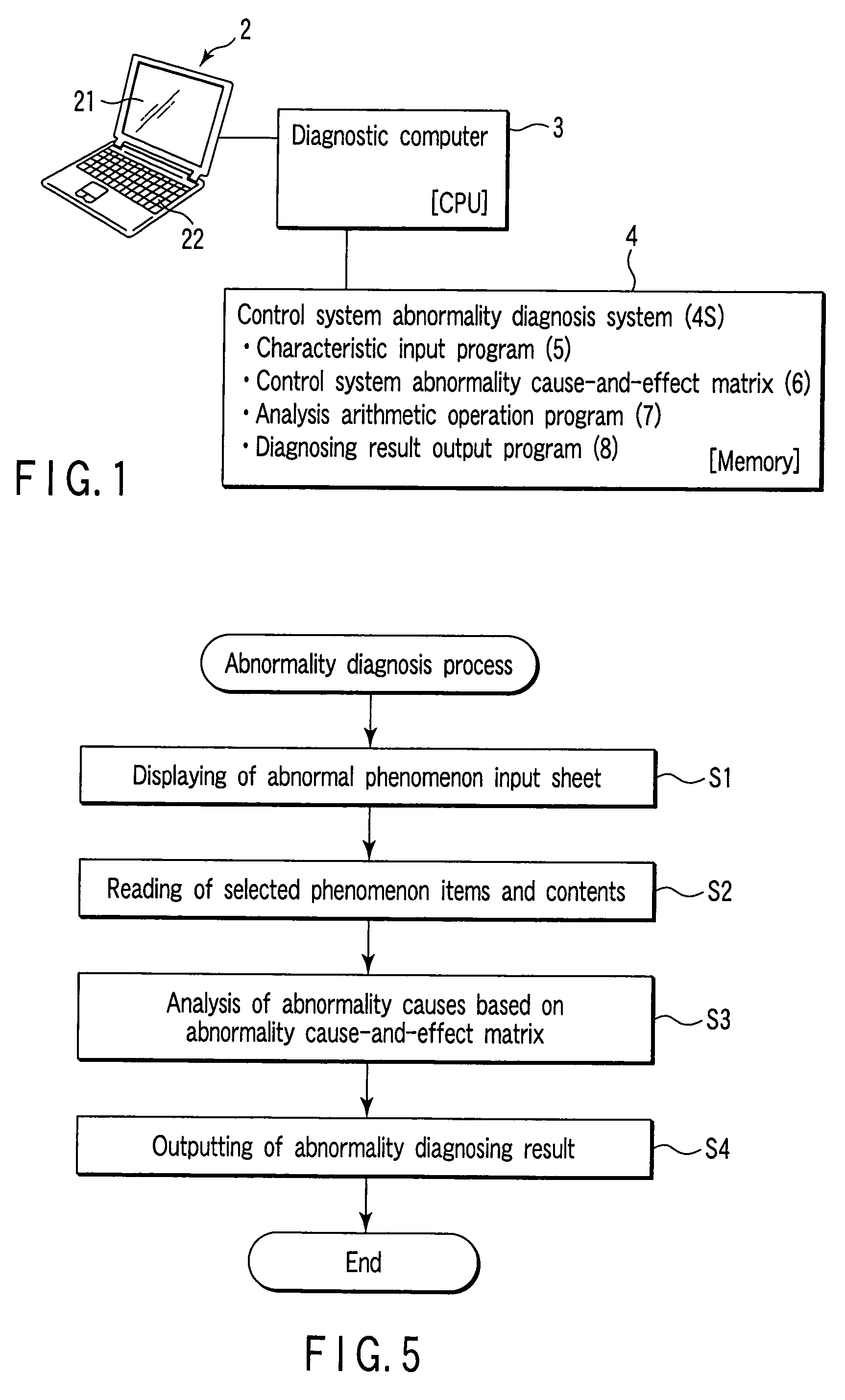
[0035]FIG. 1 is a block diagram showing a configuration of a control system abnormality diagnosis system 1 of a turbine plant according to a first embodiment of the present invention.

[0036]This control system abnormality diagnosis system 1 of the turbine plant is implemented by a personal computer (PC) 2 which uses a CPU as a diagnostic computer 3.

[0037]The diagnostic computer (CPU) 3 performs an abnormality diagnosis process of a control system of a target plant in accordance with control system abnormality diagnosis system application software 4S recorded in a memory 4 which comprises a hard disk drive and a magnetic disk unit. This control system abnormality diagnosis system application software 4S is started in accordance with a user interface by a monitor (display unit) 21 and a keyboard (input unit) 22 of the personal computer 2 to operate the diagnostic computer 3.

[0038]The control system abnormality diagnosis system application software 4S recorded in...

second embodiment

[0075](Second Embodiment)

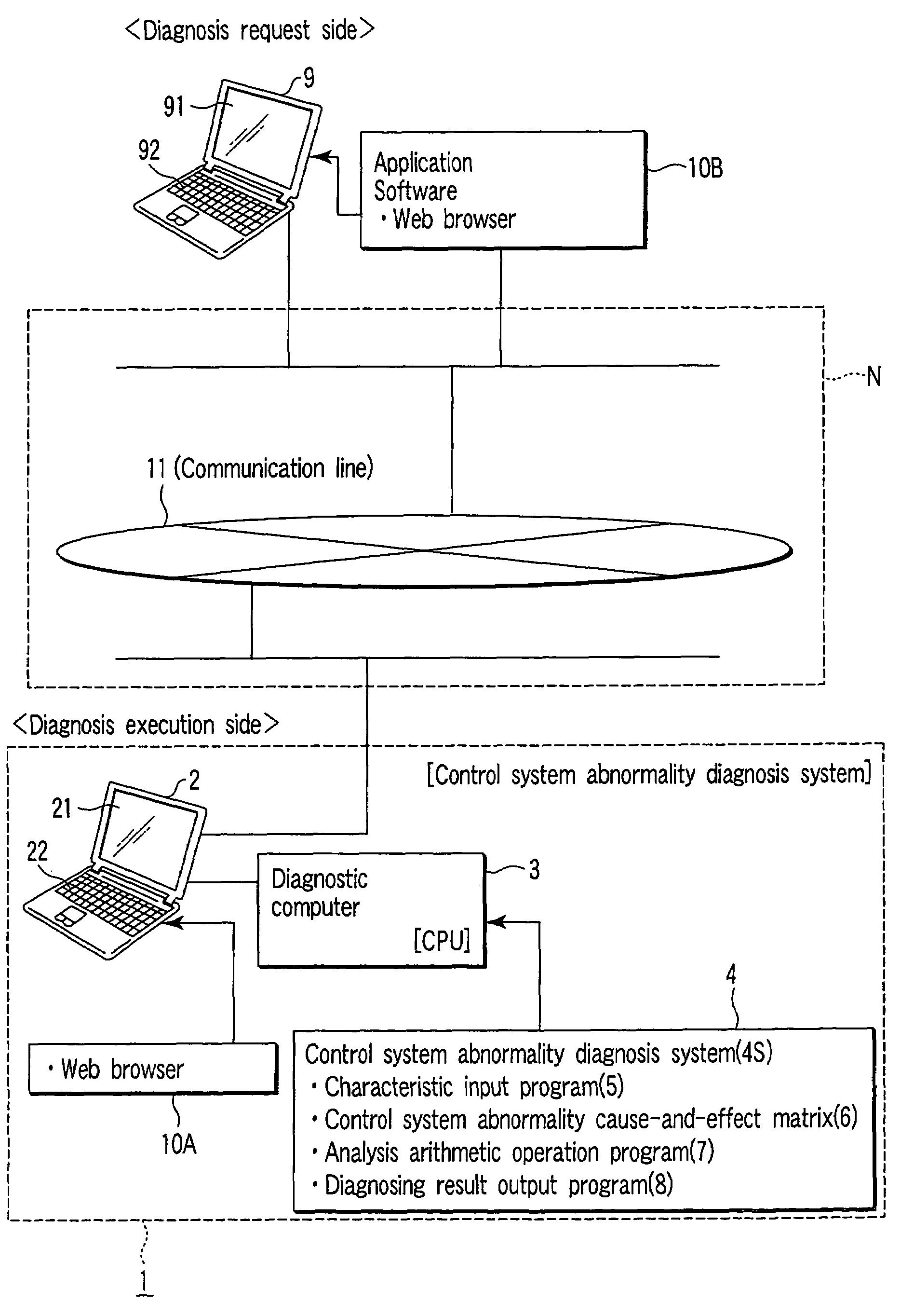
[0076]FIG. 8 is a block diagram showing a configuration of a control system abnormality diagnosis system 1 of a turbine plant connected to a network according to a second embodiment of the present invention.

[0077]A configuration is employed in which a Web browser 10A is preinstalled in a personal computer 2 of the control system abnormality diagnosis system 1 installed on a such as a manufacturer to enable access by an external computer terminal through a communication network N.

[0078]A computer terminal of a such as a user is configured as a personal computer 9 to enable access through the communication network N by preinstalling a Web browser 10B. When abnormalities occur in the control system, a primary diagnosis can be made of the control system abnormalities by easily accessing the control system abnormality diagnosis system 1 installed on the such as the manufacturer.

[0079]That is, the personal computer 2 of the control system abnormality diagnosis ...


PUM


Abstract

Cause of abnormalities of an abnormal state of a control system of a plant of a turbine are estimated and diagnosed from characteristics of abnormal phenomena. By using a control system abnormality cause-and-effect matrix in which characteristics of a plurality of abnormal phenomena constructed on a knowledge base are correlated with a plurality of causes by correlating (weighting) scores, plant devices causing abnormality are inferred and diagnosed.

Description

CROSS-REFERENCE TO RELATED APPLICATIONS[0001]This is a Continuation Application of PCT Application No. PCT / JP03 / 11727, filed Sep. 12, 2003, which was published under PCT Article 21(2) in Japanese.[0002]This application is based upon and claims the benefit of priority from prior Japanese Patent Application No. 2002-283519, filed Sep. 27, 2002, the entire contents of which are incorporated herein by reference.BACKGROUND OF THE INVENTION[0003]1. Field of the Invention[0004]The present invention relates to a system and a method for diagnosing abnormalities in a plant control system to specify a device which is an abnormality cause by inputting characteristics of an abnormal control state in a plant such as a turbine plant.[0005]2. Description of the Related Art[0006]Generally, a steam turbine of a thermal power plant adjust a rotating speed, load torque, an increase rate of the rotating speed by controlling steam supplied to the turbine.[0007]FIG. 9 is a diagram showing a steam flow of ...

Claims


Application Information

Patent Timeline
Patent Type & Authority Patents(United States)
IPC IPC(8): G06F15/00F01D25/00G05B23/02
CPCG05B23/0281
Inventor WATANABE, SHUNZOHOSAKA, HIDEOOKAZAKI, MITSUYOSHIASATSU, SEIICHIYAMASHITA, TATSUO
Owner KK TOSHIBA
Why Eureka
Try Eureka