Battery-operated can opener

a battery-operated, can opener technology, applied in the field of can openers, can solve the problems of inconvenient use of the effort required to use a conventional can opener to open a can is larg

Inactive Publication Date: 2007-05-08
LEE HUI LING
View PDF16 Cites 13 Cited by
  • Summary
  • Abstract
  • Description
  • Claims
  • Application Information

AI Technical Summary

Problems solved by technology

It is inconvenient to use a conventional can opener to open a can.
Further, using a conventional can opener to open a can requires much effort.

Method used


Image

  • Battery-operated can opener
  • Battery-operated can opener
  • Battery-operated can opener

Examples


Embodiment Construction

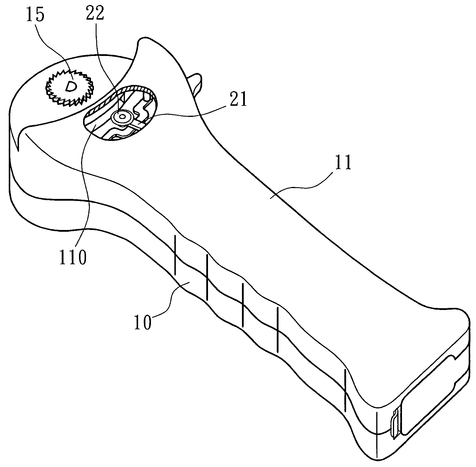
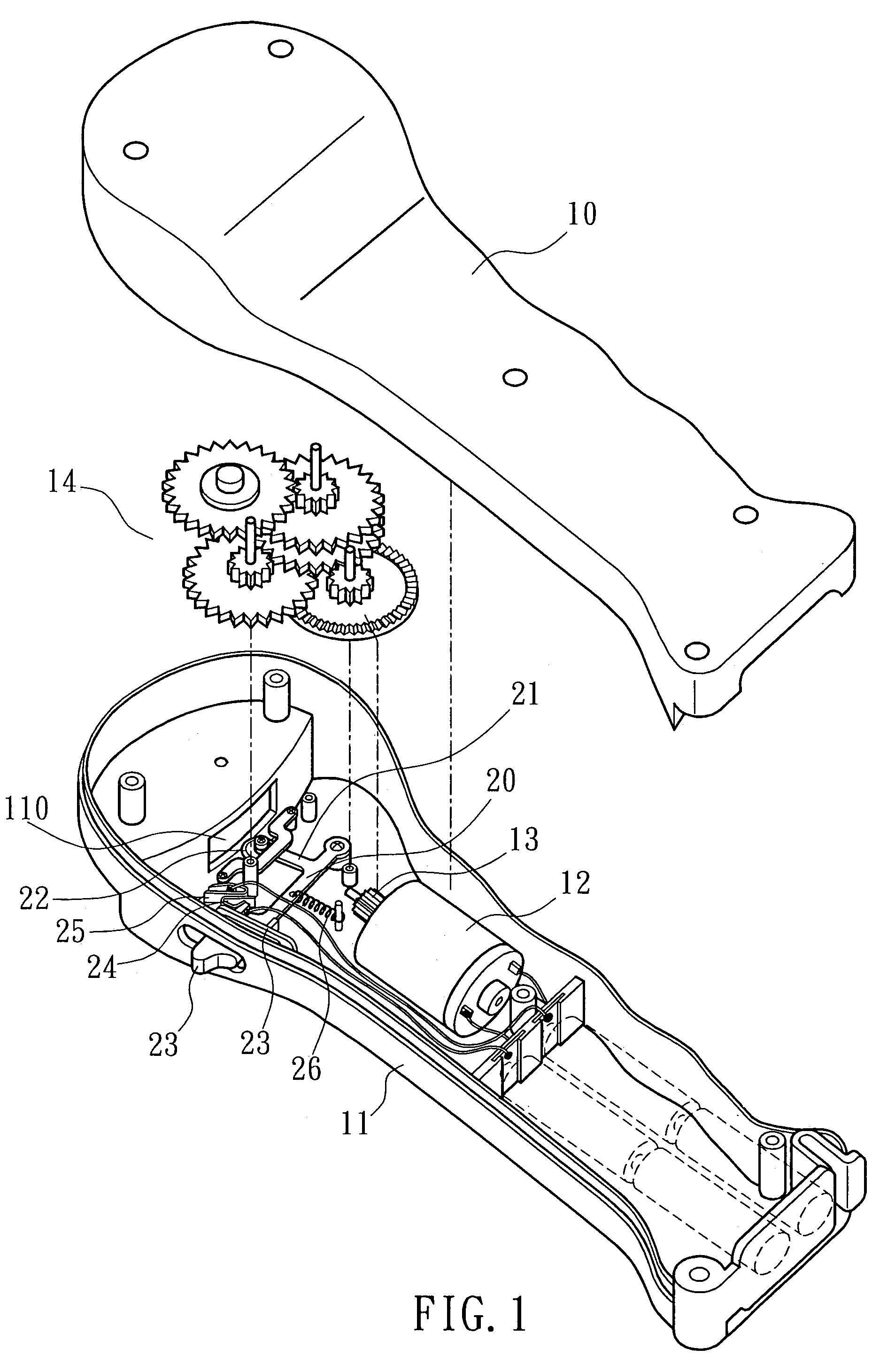
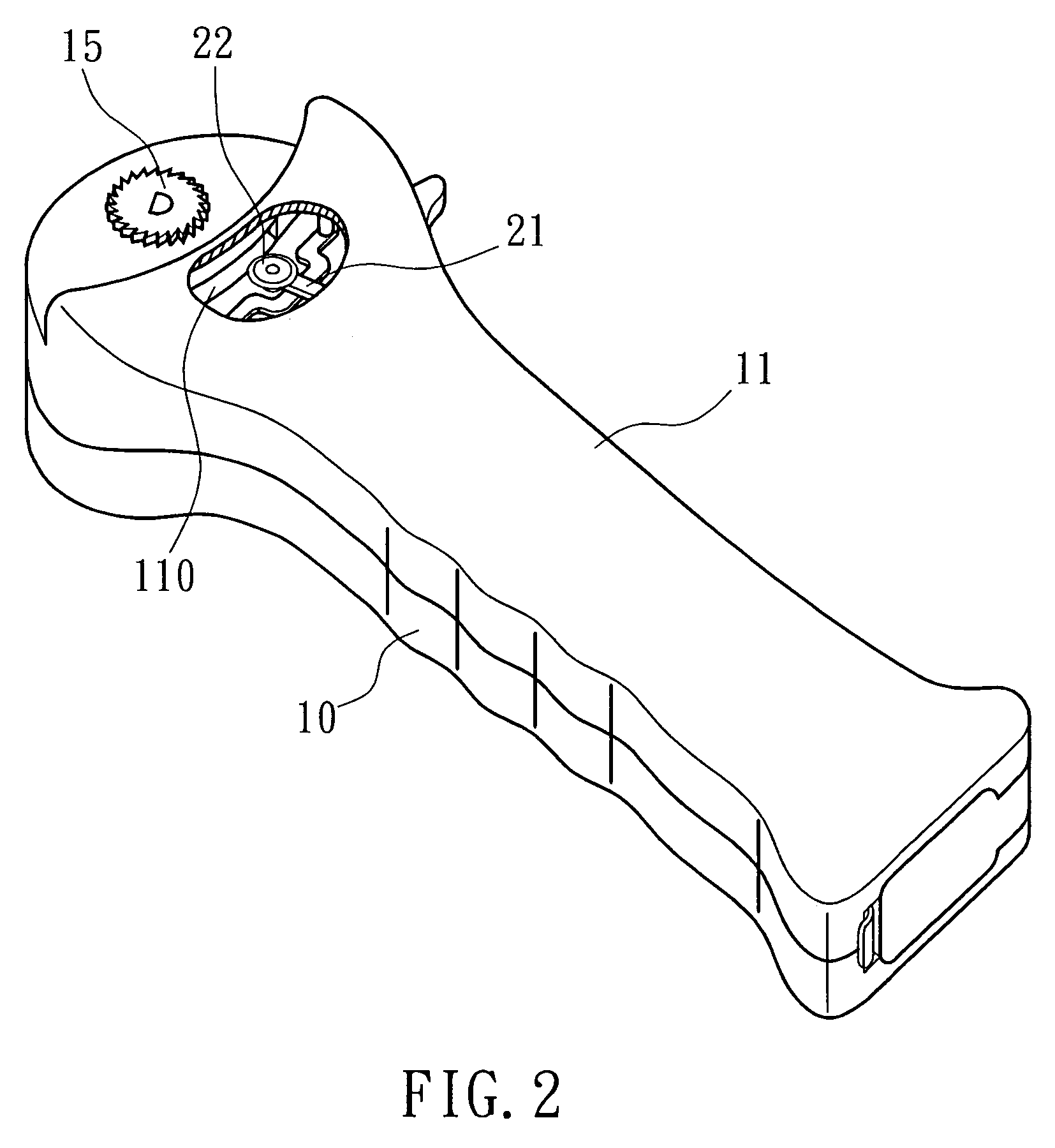
[0010]Referring to FIGS. 1 and 2, a battery-operated can opener in accordance with the present invention is shown comprising a bottom cover shell 11, a top cover shell 10 covering the bottom cover shell 11, a DC motor 12 mounted in the bottom cover shell 11, a pinion 13 fixedly mounted on the output shaft of the DC motor 12, a transmission gear set 14 mounted inside the bottom cover shell 11 and coupled to the pinion 13, a switching lever 23 pivotally mounted in one side of the bottom cover shell 11 and partially extending out of the bottom cover shell 11 for operation by hand, a first metal contact 25 fixedly mounted inside the bottom cover shell 11 and electrically connected to one pole of the battery inside the bottom cover shell 11 and one pole of the DC motor 12, a second metal contact plate 24 fixedly mounted on one end of the switching lever 23 and electrically connected to the other pole of the battery inside the bottom cover shell 11 and the other pole of the DC motor 12 an...


PUM


Abstract

A battery-operated can opener includes a DC motor, a battery, a switching lever that controls electric connection between the battery and the DC motor, an actuating arm coupled to the switching lever for moving a cutter out of the can opening for cutting the lid of a can when switching on the DC motor, a guide gear wheel coupled to the DC motor through a transmission gear set for moving the can opener along the rim of the can to force the cutter to cut open the lid of the can.

Description

BACKGROUND OF THE INVENTION[0001]1. Field of the Invention[0002]The present invention relates to a can opener and more particularly, to a battery-operated can opener.[0003]2. Description of the Related Art[0004]A conventional can opener is a hand tool having a handle and a cutter at one side of the handle. When opening a can, the user must bias the can opener and move the can opener along the rim of the can. It is inconvenient to use a conventional can opener to open a can. Further, using a conventional can opener to open a can requires much effort. When biasing a can opener to open a can, the can opener may slip from the rim of the can.SUMMARY OF THE INVENTION[0005]The present invention has been accomplished under the circumstances in view. According to one aspect of the present invention, the battery-operated can opener comprises a DC motor, a battery, a switching lever that controls electric connection between the battery and the DC motor, an actuating arm coupled to the switchin...

Claims


Application Information

Patent Timeline
Patent Type & Authority Patents(United States)
IPC IPC(8): B67B7/46
CPCB67B7/385
Inventor LEE, HUI-LING
Owner LEE HUI LING
Why Eureka
Try Eureka