Compressible fluid pressure actuator

a technology of compressible fluid and actuator, which is applied in the direction of servomotors, machines/engines, manufacturing tools, etc., can solve the problems of actuators, actuator response, actuator drop, etc., and achieve the effects of enhancing response, maintaining flexibility, and ensuring safety

Active Publication Date: 2007-05-08
PANASONIC CORP
View PDF18 Cites 8 Cited by
  • Summary
  • Abstract
  • Description
  • Claims
  • Application Information

AI Technical Summary

Benefits of technology

[0035]According to the present invention, a compressible fluid pressure actuator that can enhance response with respect to the movement at high acceleration where response is required, and that maintains flexibility with respect to the movement at low acceleration where safety is important can be obtained. That is, according to the present invention, by arranging an inner space connected to a pressure source and one or more inner spaces with respect to the flow of the compressible fluid connected by way of one or more pressure loss parts and being independent of the pressure of the first inner space (i.e., volume does not change by the pressure of the first inner space), the effects similar to when the volume occupied by the compressible fluid with respect to the entire inner space is reduced can be obtained even if the volume of the inner space is not actually changed when the pressure of the pressure source is rapidly changed, and the effects similar to when the entire inner space is one space can be obtained when static load is applied from the outside, whereby the compressible fluid pressure actuator in which the response is enhanced with respect to the movement at high acceleration where response is required, and in which the flexibility is maintained with respect to the movement at low acceleration where safety is important can be obtained.
[0036]More specifically, the pressure of the inner space connected thereto by way of the pressure loss part follows the pressure of the inner space connected to the pressure source with a delay since the compressible fluid flowing in the former inner space is small. Thus, when the pressure of the pressure source is rapidly changed, effects similar to when the volume occupied by the compressible fluid with respect to the entire inner space is reduced can be obtained since the influence of the inner space connected by way of the pressure loss part is reduced. When static load is applied from the outside, effects similar to when the entire inner space is one space can be obtained since the pressure gradually changes and thus the pressure of the inner space connected to the pressure source and the pressure connected thereto by way of the pressure loss part are substantially the same.

Problems solved by technology

Increasing the generative force or the displacement of the pneumatic actuator is achieved by enlarging the pneumatic actuator, but in such case, the amount of consumption of the compressible fluid increases since the volume of the inner space increases, and thus the response of the pneumatic actuator lowers as an issue.
A similar pneumatic actuator is also disclosed in Japanese Examined Patent Publication No. 5-67397, but has a similar issue in that the response of the pneumatic actuator lowers due to change in the volume of the inner space.
Although the pneumatic actuator of FIG. 10 described above enhances response by reducing the volume occupied by the compressible fluid with respect to the entire inner space, the flexibility, which is a characteristic of the pneumatic actuator, is lost as an issue.

Method used


Image

  • Compressible fluid pressure actuator
  • Compressible fluid pressure actuator
  • Compressible fluid pressure actuator

Examples


first embodiment

(First Embodiment)

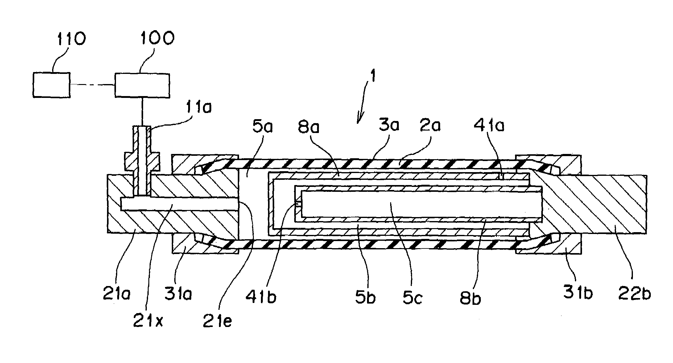
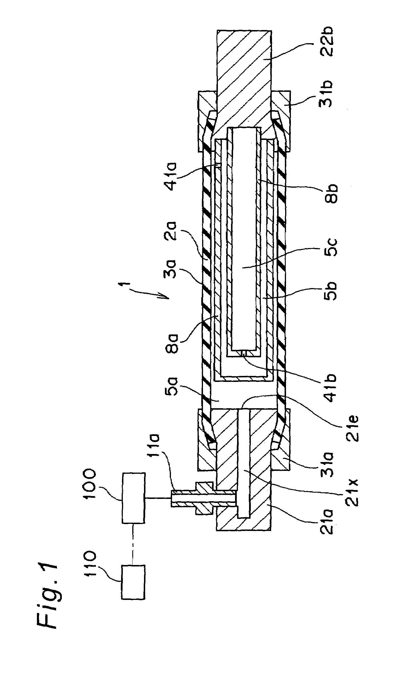
[0095]FIG. 1 is a cross sectional view showing an outline of a pneumatic actuator 1 serving as one example of a compressible fluid pressure actuator according to a first embodiment of the present invention. In FIG. 1, reference numeral 2a is a first tube-like elastic body, which includes a space inside and is made of rubber or rubber-like elastic body, functioning as one example of a first tubular expandable member. Reference numeral 3a is a deforming direction regulating member, in which resin or metal fiber code that is not easily stretched in terms of material is woven in a mesh shape so that the deformation in the radial direction due to the expansion of the first tube-like elastic body 2a is converted to the contraction of the length in the axial direction and so that the deformation in the radial direction due to the contraction of the first tube-like elastic body 2a is converted to the expansion of the length in the axial direction, and is arranged so as to ...

second embodiment

(Second Embodiment)

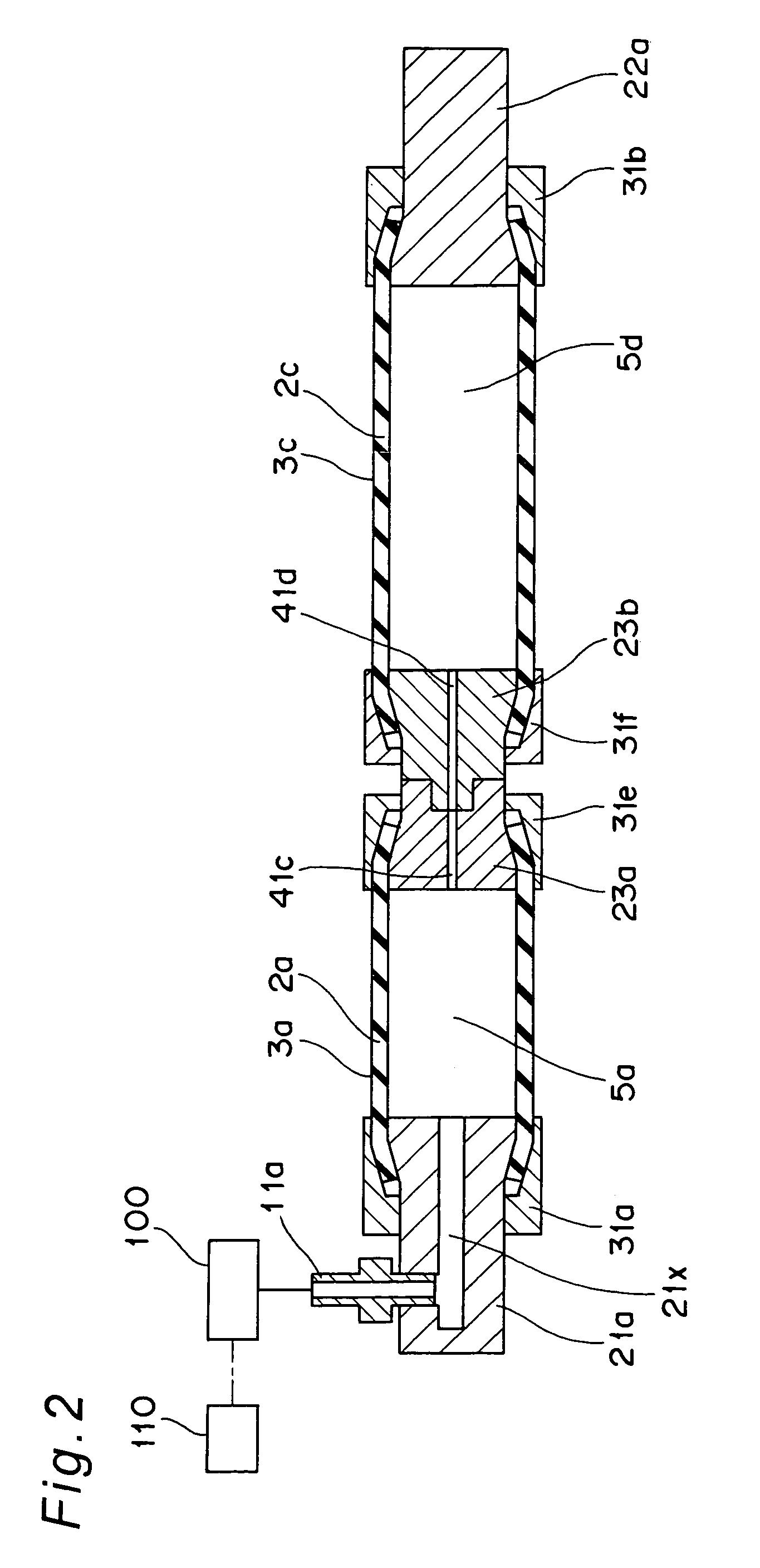
[0104]FIG. 2 is a cross sectional view showing the outline of a second embodiment of the pneumatic actuator according to the present invention. The portions functioning similar to the first embodiment described above are denoted with the same reference characters and redundant explanation is omitted. In the second embodiment, both ends of the first tube-like elastic body 2a are sealed with the inner side sealing parts 21a, 23a serving as one example of sealing means and the outer side sealing parts 31a, 31e serving as one example of the fixed means with respect to the pneumatic actuator including the first tube-like elastic body 2a. Both ends of the second tube-like elastic body 2c serving as one example of the second tubular expandable member, which exterior surface is covered by the deforming direction regulating member 3c similar to the deforming direction regulating member 3a, are sealed with the inner side sealing parts 22a, 23b serving as one example of the ...

third embodiment

(Third Embodiment)

[0110]FIG. 5 is a cross sectional view showing an outline of a third embodiment of the pneumatic actuator according to the present invention. The portions functioning similar to the second embodiment described above are denoted with the same reference characters and redundant explanation is omitted. In third embodiment, the first and second bellows shaped elastic bodies 4a, 4b are used in place of the first and the second tube-like elastic bodies 2a, 2c in the second embodiment. The entire length of the tube-like elastic body becomes short as the inner pressure increases, whereas the entire length of the first and second bellows shaped elastic bodies 4a, 4b becomes long as the inner pressure increases. However, since the pneumatic actuator using the first and second bellows shaped elastic bodies 4a, 4b similarly exhibits the response of substantially primary delay system, no significant difference exists in the effect of arranging the pressure loss part. Thus, the ...


PUM


Abstract

An inner space connected to a power source and an inner space connected by way of a pressure loss part with respect to the flow of compressible fluid are provided, thereby obtaining effects similar to when the volume occupied by the compressible fluid with respect to the entire inner space is reduced when the pressure of the pressure source is rapidly changed, and effects similar to when the entire inner space is one space when static load is applied from the outside.

Description

[0001]This is a continuation application of International Application No. PCT / JP2004 / 012182, filed Aug. 25, 2004.BACKGROUND OF THE INVENTION[0002]The present invention relates to a compressible fluid pressure actuator.[0003]A pneumatic actuator using compressible fluid has been proposed and put to practical use as one of the actuators suited to a field of domestic robots and the like where safety is important. The Mckibben pneumatic actuator shown in FIG. 9 is proposed as one example of the pneumatic actuator. The Mckibben pneumatic actuator has a configuration in which a restricting means 303a configured by a fiber cord is arranged on the exterior surface of a tube-like elastic body 302a made of a rubber material, where both ends of the tube-like elastic body 302a are sealed in an air tight manner with the inner side sealing parts 321a, 322a and the fixed means 331a, 331b. When inner pressure is provided to the inner space 305a of the tube-like elastic body 302a with compressible f...

Claims


Application Information

Patent Timeline
Patent Type & Authority Patents(United States)
IPC IPC(8): F01B19/04B25J9/10B25J9/14F15B11/04F15B11/06F15B15/10
CPCB25J9/1075B25J9/142F15B11/04F15B11/06F15B15/103F15B2211/40507F15B2211/7052F15B2211/755
Inventor ASAI, KATSUHIKOOKAZAKI, YASUNAOYAMAMOTO, MASAKI
Owner PANASONIC CORP
Why Eureka
Try Eureka