Light source apparatus, lighting apparatus and projection display apparatus

a technology of projection display and light source, which is applied in the direction of lighting and heating apparatus, point-like light sources, instruments, etc., can solve the problems of large size of light source apparatus, loss of much of light passing through the light-emitting portion, and large outer shape of light source apparatus

Active Publication Date: 2007-05-08
PANASONIC CORP
View PDF17 Cites 17 Cited by
  • Summary
  • Abstract
  • Description
  • Claims
  • Application Information

AI Technical Summary

Problems solved by technology

It also has a problem that its outer shape becomes large.
However, the light source apparatus of the second conventional example shown in FIG. 15 has the following problem.
However, this leads to a larger size of the light source apparatus so that the light collection efficiency and the larger size of the light source apparatus will be in a trade-off relation.
In the case of using a metal halide lamp or a mercury lamp as the lamp, much of the light passing through the light-emitting portion again is lost due to light absorption and light scattering of light-emitting materials and materials configuring the lamp.
Thus, it has a problem that the amount of luminous fluxes emitted to the focus Y is consequently reduced and optical usable efficiency is lowered as the entire light source apparatus.

Method used


Image

  • Light source apparatus, lighting apparatus and projection display apparatus
  • Light source apparatus, lighting apparatus and projection display apparatus
  • Light source apparatus, lighting apparatus and projection display apparatus

Examples


first embodiment

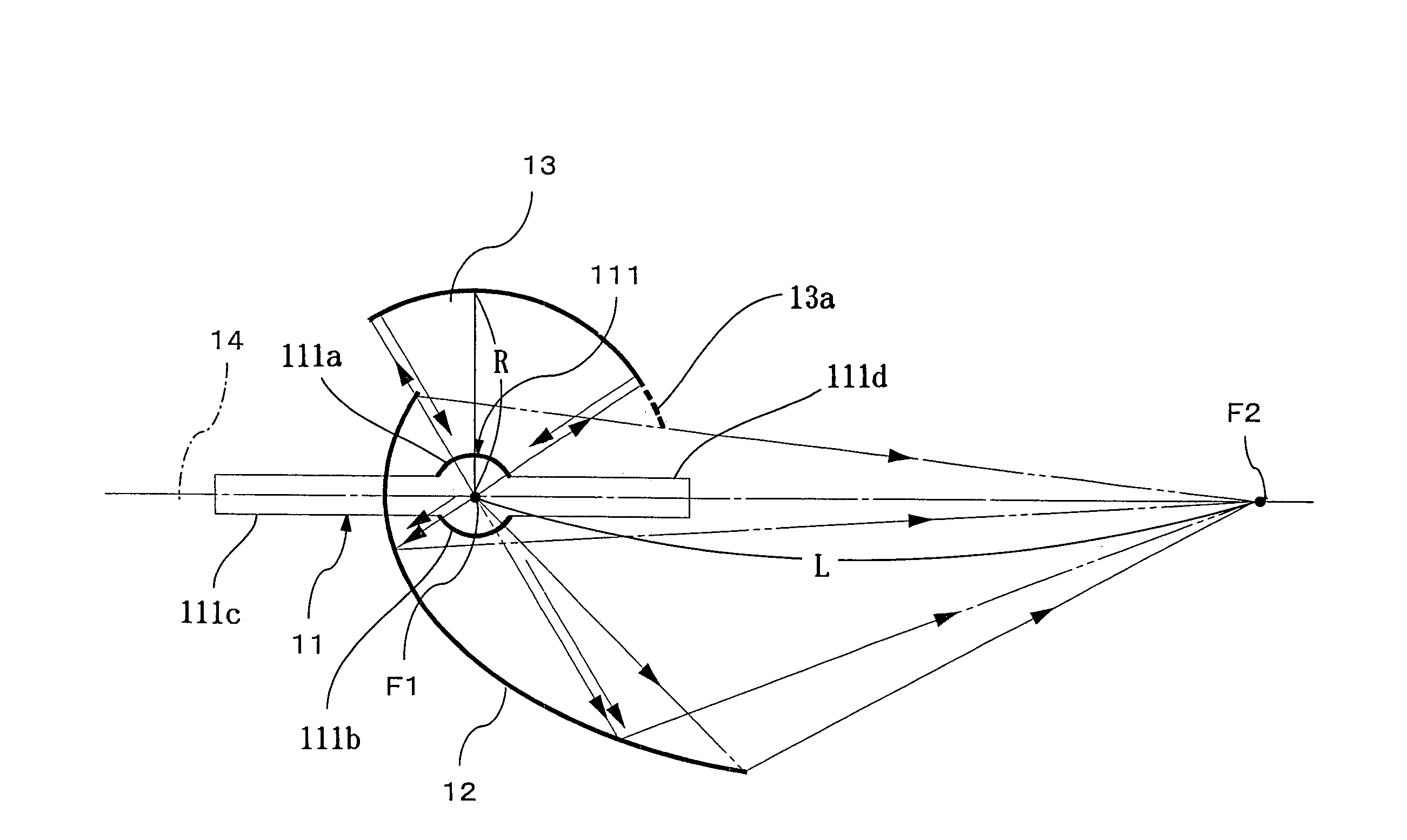
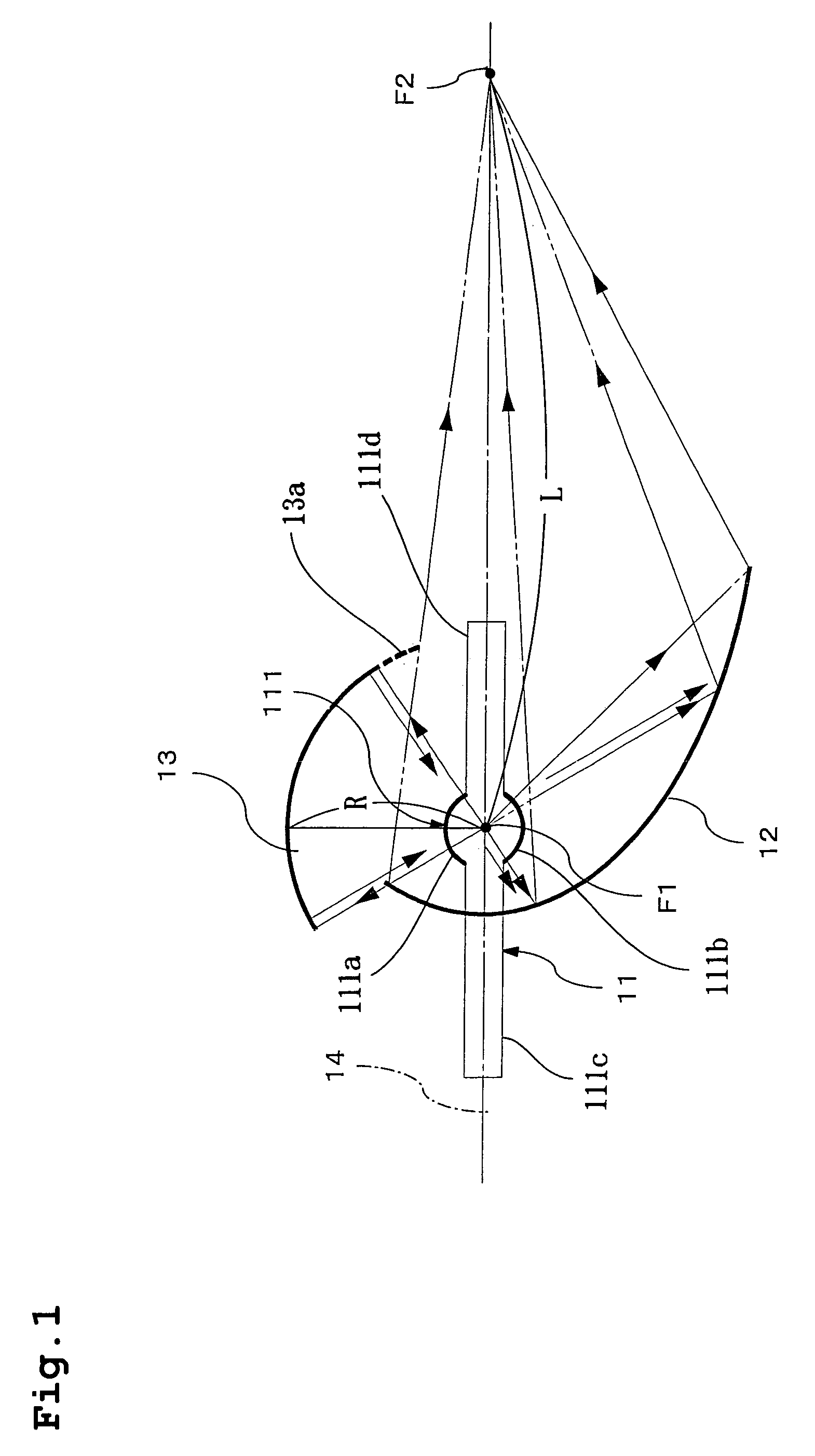
[0085]Hereunder, a first embodiment of the present invention will be described by referring to the drawings. FIG. 1 shows an overview configuration of a light source apparatus according to the first embodiment.

[0086]This light source apparatus is configured by a lamp (an example of the lamp or light generating means of the present invention) 11, an ellipsoidal mirror (an example of a first concave mirror of the present invention) 12 and a spherical mirror (an example of a second concave mirror of the present invention) 13.

[0087]The lamp 11 is configured by a lamp light-emitting portion 111 having a substantially spherical vessel portion including a source of luminescence positioned correspondingly to a focal position mentioned later and generating light, and light transmission planes 111a and 111b containing the source of luminescence and transmitting the light therefrom to the outside, and a pair of ends 111c and 111d including electrodes of the source of luminescence and having a ...

second embodiment

[0123]Hereunder, a second embodiment of the present invention will be described by referring to the drawings. FIGS. 8 and 10 show overview configurations of the lighting apparatus and the projection display apparatus according to this embodiment.

[0124]The light source apparatus 100 is the same as that in the first embodiment, and so a description thereof will be omitted. As previously described, a multi-lamp optical system as shown in FIG. 11 uses multiple light source apparatuses to be able to perform brighter illumination, combines the luminous fluxes emitted from each of the multiple light source apparatuses and has them incident on one piece of rod integrator or lens optical system to perform the illumination.

[0125]In the case of the optical system using a rod integrator 2 shown in FIG. 11, it is necessary, for the sake of reducing the loss in the optical system from the rod integrator 2 onward and improving the optical usable efficiency of the luminous fluxes emitted from the l...

third embodiment

[0150]FIG. 18 shows the configuration of the lighting apparatus according to a third embodiment of the present invention. In FIG. 18, the rod integrator 101, a relay lens 102 and the light modulation device 105 are the same as the conventional examples and the second embodiment. To be more specific, it has the configuration in which the light source apparatus according to the first embodiment is used as the light source apparatus of the lighting apparatus of the conventional example shown in FIG. 11. In this case, the pair of light source apparatuses 100 is placed to have their spherical mirrors 13 opposed to each other, and the rod integrator 101 is placed at an intersection which is a point in space at which the optical axes 14 of the light source apparatuses 100 intersect.

[0151]The lighting apparatus of this embodiment has the same optical operation as the conventional example of FIG. 11. It uses the light source apparatuses of the first embodiment as the pair of light source app...


PUM


Abstract

A light source apparatus includes a lamp, an ellipsoidal mirror collecting a part of light radiated from a light transmission plane of the lamp, and a spherical mirror collecting another part of the light radiated from a light transmission plane not collected by the ellipsoidal mirror and reflecting it on the ellipsoidal mirror, in which a reflection plane of the ellipsoidal mirror and the reflection plane of the spherical mirror are in a form of non-rotation symmetry to an optical axis connecting a focal position F1 corresponding to a source of luminescence of the lamp to a focal position F2 of the light collected by the ellipsoidal mirror respectively. The distance between the reflection plane of the spherical mirror and the source of luminescence of the lamp is shorter than the distance between the source of luminescence and the focus of the light collected by the ellipsoidal mirror, and a part of the reflection plane of the ellipsoidal mirror is formed around the optical axis.

Description

[0001]THIS APPLICATION IS A U.S. NATIONAL PHASE APPLICATION OF PCT INTERNATIONAL APPLICATION PCT / JP2004 / 005422.TECHNICAL FIELD[0002]The present invention relates to a light source apparatus having light generating means and a concave mirror, a lighting apparatus and a projection display apparatus.BACKGROUND ART[0003]In recent years, attention is being given to a projection display apparatus using various light modulation devices as a large-screen projection video apparatus. In the case of performing a large-screen display, brightness of a displayed image can be named as the most important item.[0004]Thus, attention is being given to a multi-lamp illumination system using multiple lamps and capable of improving optical output as the projection display apparatus. As for the brightness, it is important to illuminate the light modulation device as an image display device with as little loss of luminous fluxes radiated from the lamps as possible, that is, as efficiently as possible. For ...

Claims


Application Information

Patent Timeline
Patent Type & Authority Patents(United States)
IPC IPC(8): F21V7/00F21V7/09F21Y101/00G03B21/20
CPCF21V7/0025F21V7/09G03B21/2026G03B21/2013
Inventor SHIMAOKA, YUSAKUNAMBA, SHUTANABE, KAZUNORI
Owner PANASONIC CORP
Why Eureka
Try Eureka