Device for manufacturing a double-walled thermoplastic pipe with a connecting sleeve

a technology of thermoplastic pipes and connecting sleeves, which is applied in the direction of manufacturing tools, hollow wall articles, dough shaping, etc., can solve the problems of imposing very large pressure control demands, particularly difficult, and subjecting space a

Active Publication Date: 2007-05-08
MANFRED ARNO ALFRED LUPKE
View PDF28 Cites 9 Cited by
  • Summary
  • Abstract
  • Description
  • Claims
  • Application Information

AI Technical Summary

Benefits of technology

[0012]Therefore, one object underlying the invention is to improve the device for manufacturing a double-walled thermoplastic pipe with a connecting sleeve in such a way that, in the first portion of the molding tunnel, a curvature of the inner tube is avoided during the cooling of the flexible tubes and, in the second portion of the molding tunnel, satisfactory expansion of the first flexible tube to form a connecting sleeve is made possible.
[0014]Further, a pressure controller is connected to said first gas channel by a compressed-gas line which is connected to an additional compressed-gas reservoir for gas exchange. The compressed-gas reservoir can consequently communicate with the space A via the compressed-gas line and via the first gas channel. If, for example on account of an increase in volume of the space A, the pressure there drops, there is immediately a pressure equalization between space A and the compressed-gas reservoir, which attenuates the pressure drop in the space A. This makes it possible in a simple way to avoid to the greatest extent undesired pressure gradients in the space A, which would otherwise have to be equalized by the compressed-gas control device, which however would involve much more sophisticated closed-loop control. According to the invention, the pressure is controlled in a closed-loop or open-loop manner in a complete system, the volume of which is substantially made up by the volume of the space A and the volume of the compressed-gas reservoir. This leads to an evening-out of the pressure profile in the space A, so that in particular the undesired curvatures at the inner wall of the double-walled pipe can be avoided.
[0016]The separate vessel is preferably connected to the compressed-gas line by a T-shaped sleeve. This allows a device known from the art to be modified in a simple way, in that the compressed-gas line provided there is cut and the T-shaped sleeve with a compressed-gas vessel is inserted there.
[0019]According to a further object, the compressed-gas reservoir is arranged in the vicinity of the first gas channel. An arrangement of this type allows the flow resistances between the compressed-gas reservoir and the space A to be minimized, so that a rapid pressure equalization can take place between the compressed-gas reservoir and the space A.
[0021]A safety valve may be connected between the compressed-gas control device and the first gas channel. The valve is preferably formed as a spring-actuated valve, which closes under a specific pressure. In this way it is possible to avoid inadmissible excess pressures in the space A, for example if there is a defect of the compressed-gas control device.

Problems solved by technology

In the case of the device described above, closed-loop control of the pressures p1 and p2, to which the space A is subjected, in particular proves to be difficult.
In particular in the case of large pipe diameters, the changes in volume in the space A influence the pressures p1 and p2 to such an extent that maintaining them imposes very great demands on the pressure control.

Method used


Image

  • Device for manufacturing a double-walled thermoplastic pipe with a connecting sleeve
  • Device for manufacturing a double-walled thermoplastic pipe with a connecting sleeve
  • Device for manufacturing a double-walled thermoplastic pipe with a connecting sleeve

Examples


Embodiment Construction

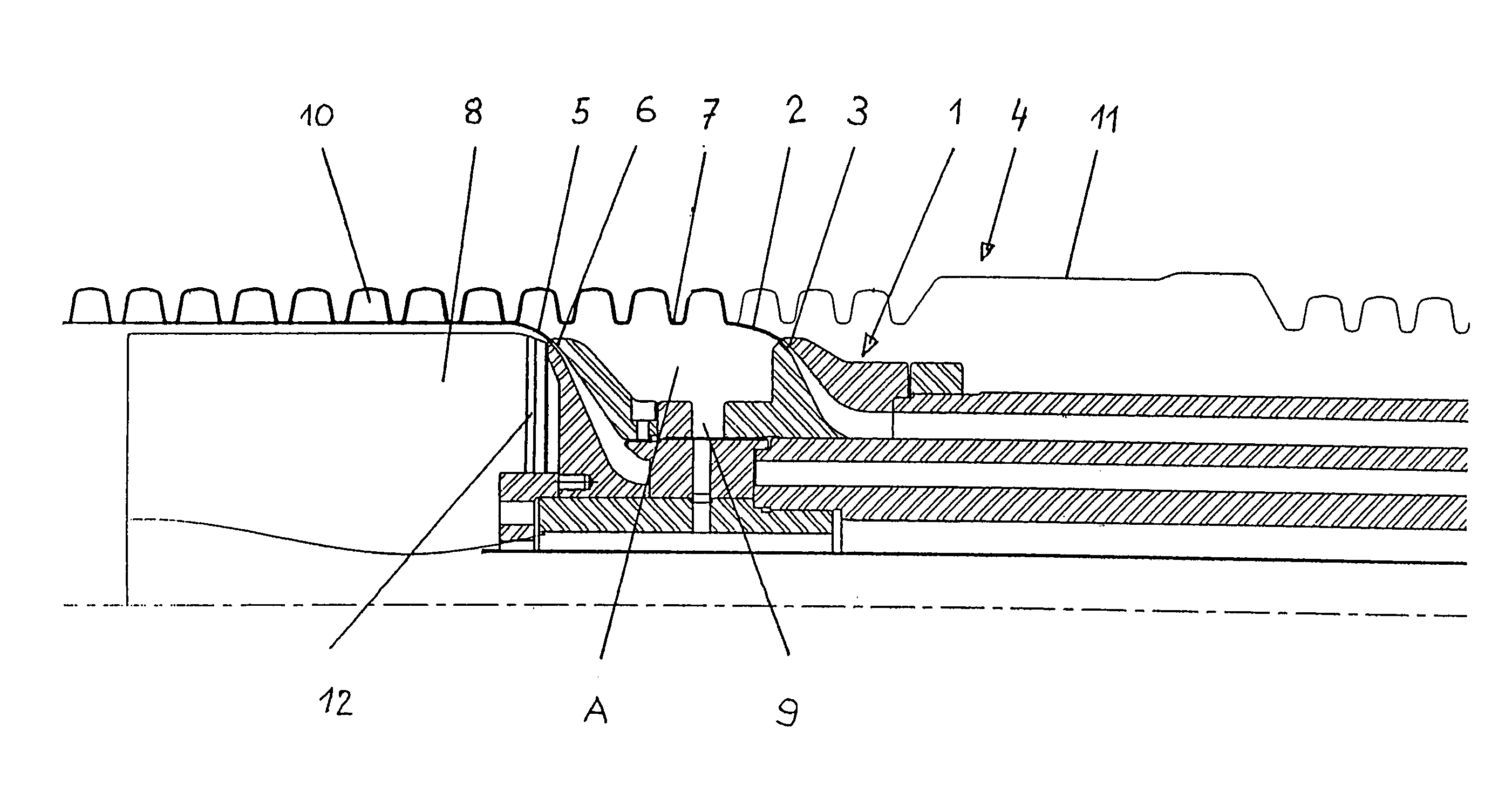
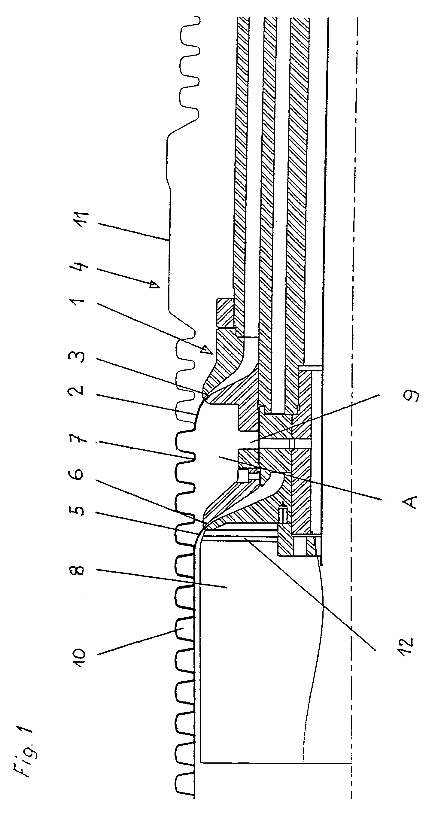
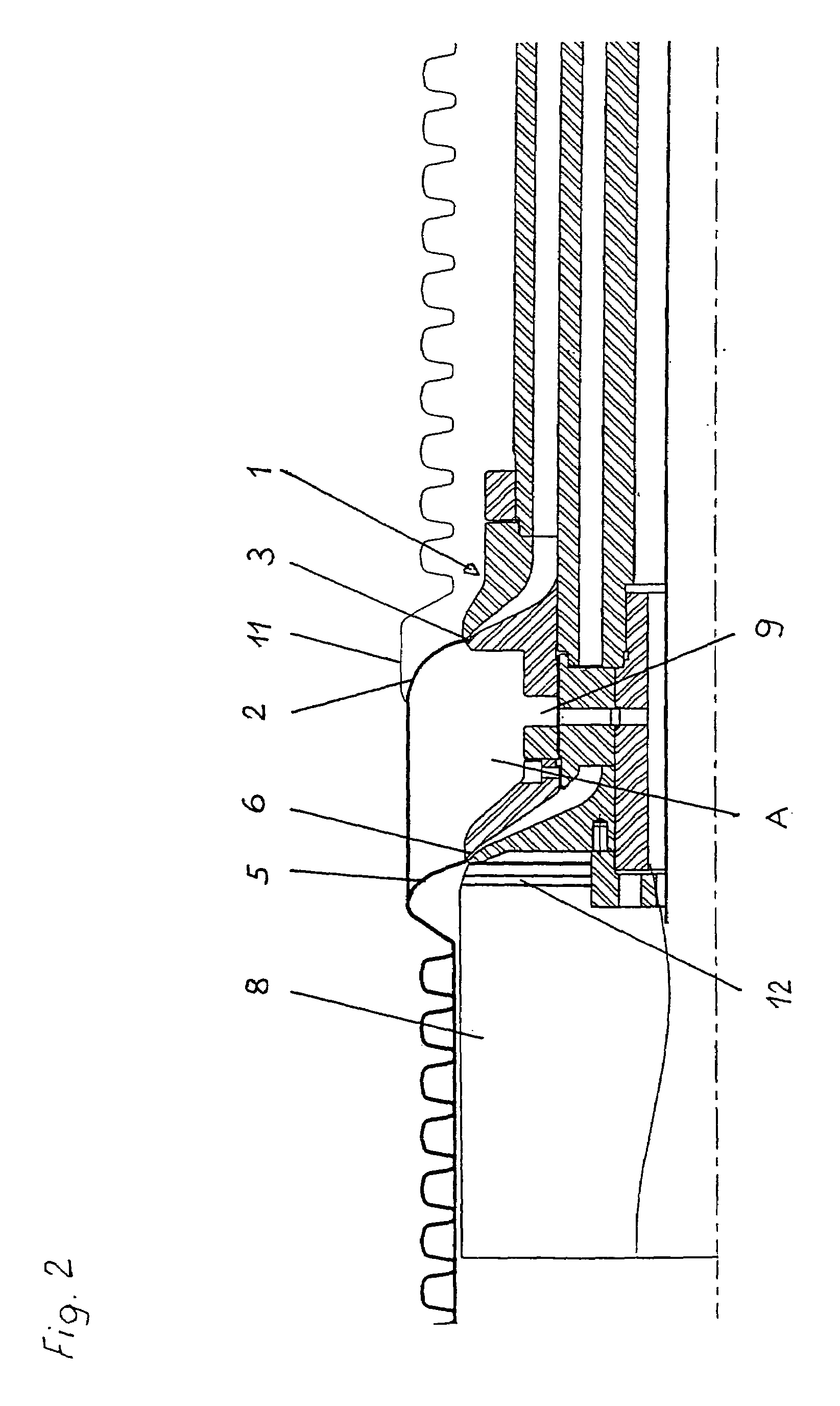
[0030]FIGS. 1 and 2 show an extrusion head 1 of the device according to the invention in various process steps. In the step represented in FIG. 1, a first flexible tube 2 is extruded through a first die 3 of the extrusion head 1 into a first portion of the molding tunnel 4 and brought into a corrugated form. A second flexible tube 5 is extruded through a second die 6 of the extrusion head 1 into the first flexible tube 2 and pressed against corrugation troughs 7 of the first flexible tube 2. Arranged downstream of the extrusion head 1 in the direction of production is a calibrating mandrel 8 for the second flexible tube 5.

[0031]While the first flexible tube 1 is being brought into the corrugated form and the second flexible tube 5 is being pressed against the corrugation troughs 7 of the first flexible tube 2 and fused with them, the space between the two flexible tubes 2 and 5, space A, is subjected to a pressure p1 lying above atmospheric pressure. The pressure is generated by a c...


PUM

PropertyMeasurementUnit
outer diameteraaaaaaaaaa
volumeaaaaaaaaaa
volumeaaaaaaaaaa

Abstract

A device for manufacturing a double-walled thermoplastic pipe with a connecting sleeve has a molding tunnel with a succession of molds for forming a corrugated molding wall and a connecting sleeve, respectively. An extrusion device extrudes a first flexible tube into said molding tunnel and a second flexible tube into said first flexible tube. A first gas channel is arranged for generating a pressure between said first and second flexible tubes. A compressed-gas control device is connected to said first gas channel for generating a pressure p1 or a pressure p2 in said space between said first and second flexible tubes by compressed air emerging from said first gas channel. A second compressed-gas control device is connected to a second gas channel for guiding compressed gas onto an inner side of said second flexible tube. Said first pressure controller is connected to said first gas channel via a compressed-gas line that is connected to an additional compressed-gas reservoir for gas exchange therewith.

Description

RELATED APPLICATION[0001]This is a continuation application of International Patent Application PCT / IB2004 / 003361, filed Jun. 23, 2004, designating the United States and published in German as WO 2005 / 009720 A1, which claims priority to German patent application number 103 35 518.9, filed Jul. 31, 2003.BACKGROUND OF THE INVENTION[0002]a. Field of the Invention[0003]The invention relates to a device for manufacturing a double-walled thermoplastic pipe with a connecting sleeve.[0004]b. Related Prior Art[0005]A device of this type is known for example from DE 101 10 064 A1. The device has a number of molds guided on a path, which form a molding tunnel, which has in at least a first portion a corrugated molding wall and in at least a second portion a sleeve recess corresponding to the connecting sleeve. An extrusion head of the device has a first die for the extrusion of a first flexible tube into the molding tunnel and a second die, arranged downstream in the direction of movement of t...

Claims


Application Information

Patent Timeline
Patent Type & Authority Patents(United States)
IPC IPC(8): B29C53/30B29C48/09B29C48/30B29C48/90B29C48/92B29C49/00B29C49/78
CPCB29C47/92B29C49/783B29C49/0021B29C47/0023B29C47/0033B29C47/065B29C47/126B29C47/261B29C49/0031B29C2791/006B29L2023/18B29L2024/00B29C48/92B29C48/09B29C48/13B29C48/21B29C48/303B29C48/336B29C2948/92514B29C2948/92904B29C2948/92942B29C49/0025
Inventor LUPKE, MANFRED ARNO ALFREDLUPKE, STEFAN A.
Owner MANFRED ARNO ALFRED LUPKE
Why Eureka
Try Eureka