Artificial intervertebral disc having an articulating joint

a technology of artificial intervertebral discs and articulating joints, which is applied in the field of spinal implant assembly, can solve the problems of collateral injury to the patient's spine, limiting the overall flexibility of the spinal column, and limiting the normal motion of the patien

Inactive Publication Date: 2007-05-08
HOWMEDICA OSTEONICS CORP
View PDF17 Cites 142 Cited by
  • Summary
  • Abstract
  • Description
  • Claims
  • Application Information

AI Technical Summary

Benefits of technology

[0025]To enhance the securing of the baseplates to the vertebral bones, each baseplate further comprises a porous area, which at least extends in a ring around the lateral rim of each outwardly facing surface. The porous area may be, for example, a sprayed deposition layer, or an adhesive applied beaded metal layer, or another suitable porous coating known in the art. The porous ring permits the long-term ingrowth of vertebral bone into the baseplate, thus permanently securing the prosthesis within the intervertebral space. The porous layer may extend beneath the domed mesh as well, but is more importantly applied to the lateral rim of the outwardly facing surface of the baseplate that seats directly against the vertebral body.
[0027]The ball and socket joint, employing a partial spherical member that is not captured, disposed between the baseplates permits rotation and angulation of the two baseplates relative to one another about a centroid of motion centrally located between the baseplates. A variety of embodiments are contemplated. In some embodiments, the joint is used in conjunction with a resilient member to additionally permit the two baseplates to axially compress relative to one another. Further in each of the embodiments, the assembly prevents lateral translation of the baseplates during rotation and angulation.
[0029]Each of the embodiments discussed herein share the same basic elements, some of which retain identical functionality and configuration across the embodiments, and some of which gain or lose functionality and / or configuration across the embodiments to accommodate mechanical and / or manufacturing necessities. More specifically, each of the embodiments includes two baseplates, each having an inwardly directed articulation surface, having a ball and socket joint disposed therebetween employing an uncaptured partial spherical member that is established centrally between the baseplates. The partial spherical member has a large radius and substantially continuous arc of curvature to minimize point loading and reduce the risk and incidence of fatigue failure. Each of the embodiments will be understood further in light of the additional descriptions of the embodiments herein.
[0033]The elongated portion of the pin member preferably comprises a continuous cylindrical cross section; however, the cross section may vary toward the distal end thereof, such as by gradually or abruptly thickening near the juncture of the elongated member and the head portion, to provide structural strength.
[0036]The curvate socket defines a spherical contour that closely accommodates the partial spherical member for free rotation and angulation. Therefore, when seated in the curvate socket, the partial spherical member can rotate and angulate freely relative to the curvate socket through a range of angles, thus permitting the opposing baseplates to rotate and angulate freely relative to one another through a corresponding range of angles equivalent to the fraction of normal human spine rotation and angulation (to mimic normal disc rotation and angulation). Because the baseplates are made angulatable relative to one another by the partial spherical member being rotatably and angulatably coupled in the curvate socket, the disc assembly provides a centroid of motion within the sphere defined by the partial spherical member. Accordingly, the centroid of motion of the disc assembly remains centrally located between the vertebral bodies, similar to the centroid of motion in a healthy natural intervertebral disc.
[0038]In other preferred embodiments of the present invention, an intervertebral device includes a first plate having an outer face and an inner face, and a second plate juxtaposed with the first plate, the second plate having an outer face, an inner face that opposes the first plate and a concavity that opposes the first plate. The device preferably includes an elongated member extending from the first plate toward the second plate, the elongated member having a distal end with a spherical surface that is engageable with the concavity of the second plate for providing an articulating joint between the first and second plates. The device also desirably includes a resilient member in contact with the elongated member for counteracting compressive loads on the plates, whereby the resilient member is surrounded by the concavity of the second plate.

Problems solved by technology

It is, however, important to note that the fusion of the adjacent bones is an incomplete solution to the underlying pathology as it does not cure the ailment, but rather simply masks the pathology under a stabilizing bridge of bone.
This bone fusion limits the overall flexibility of the spinal column and artificially constrains the normal motion of the patient.
This constraint can cause collateral injury to the patient's spine as additional stresses of motion, normally borne by the now-fused joint, are transferred onto the nearby facet joints and intervertebral discs.

Method used


Image

  • Artificial intervertebral disc having an articulating joint
  • Artificial intervertebral disc having an articulating joint
  • Artificial intervertebral disc having an articulating joint

Examples


Embodiment Construction

[0048]While the invention will be described more fully hereinafter with reference to the accompanying drawings, in which particular embodiments and methods of implantation are shown, it is to be understood at the outset that persons skilled in the art may modify the invention herein described while achieving the functions and results of the invention. Accordingly, the descriptions that follow are to be understood as illustrative and exemplary of specific structures, aspects and features within the broad scope of the invention and not as limiting of such broad scope. Like numbers refer to similar features of like elements throughout.

[0049]A preferred embodiment of the present invention will now be described.

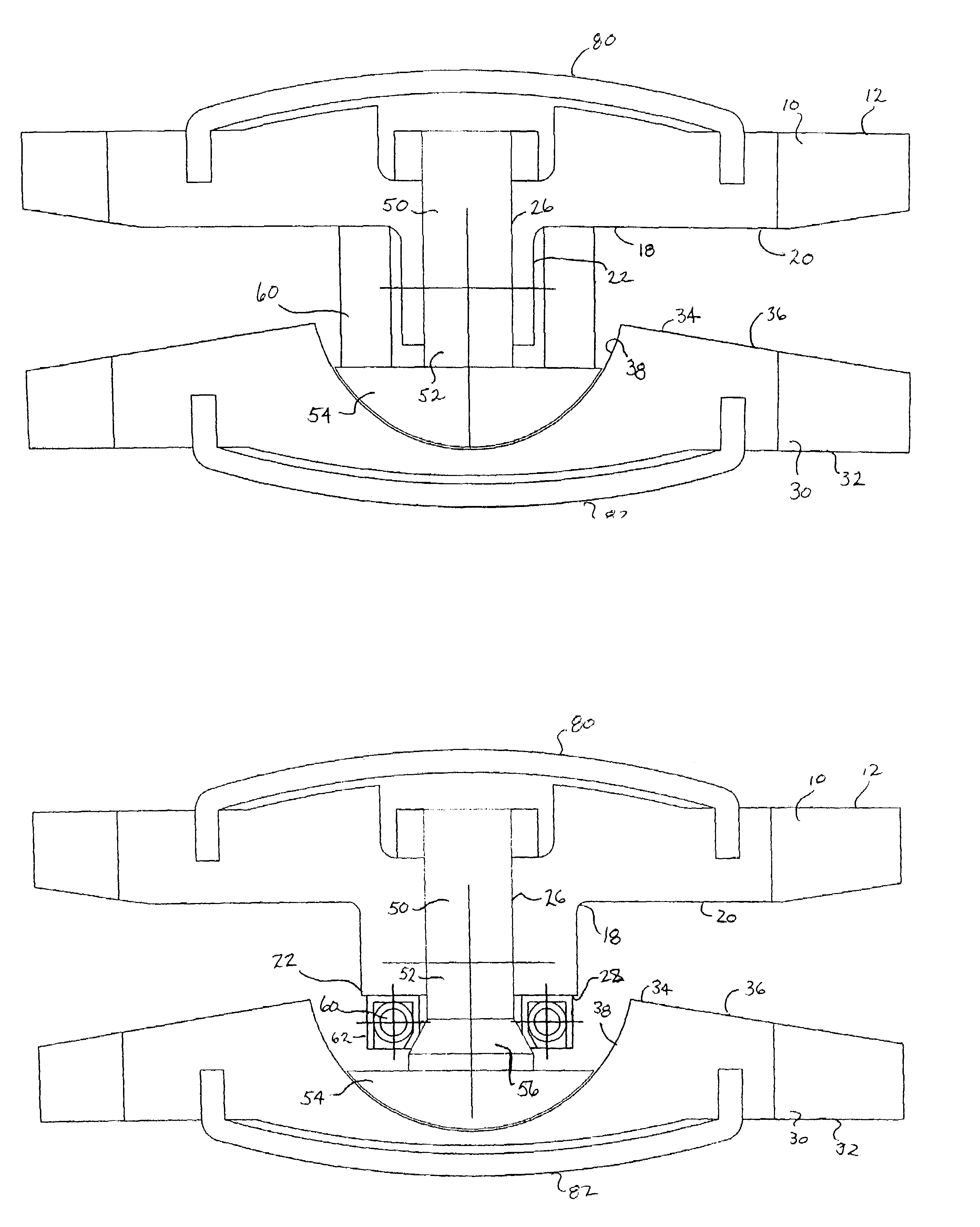
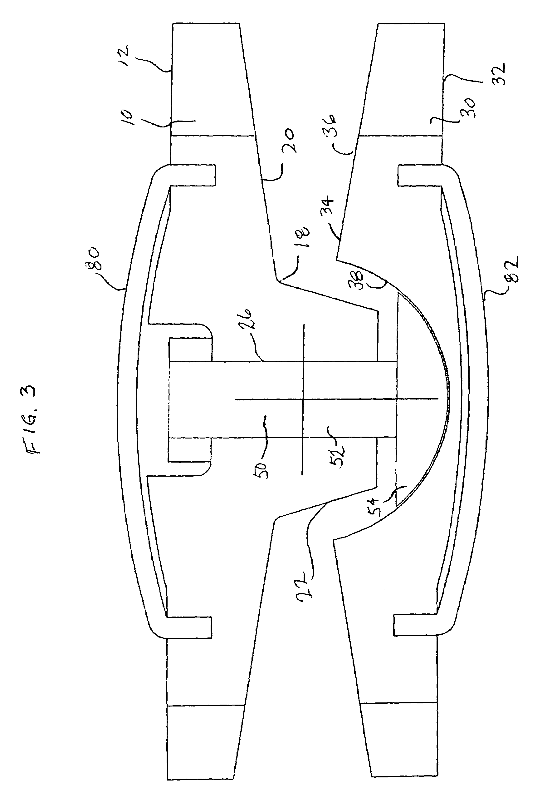
[0050]Referring to FIG. 3, the invention is shown having a first baseplate 10 and a second baseplate 30 and a pin 50. Each baseplate 10,30 has an outwardly facing surface 12,32. Because the artificial disc of the invention is to be positioned between the facing surfaces of adjacen...


PUM


Abstract

An intervertebral device includes a first plate having an outer face and an inner face, and a second plate juxtaposed with the first plate, the second plate having an outer face, an inner face that opposes the first plate and a concavity that opposes the first plate. The device includes an elongated member extending from the first plate toward the second plate, the elongated member having a distal end with a spherical surface that is engageable with the concavity of the second plate for providing an articulating joint between the first and second plates. The device also includes a resilient member in contact with the elongated member for counteracting compressive loads on the plates, the resilient member being surrounded by the concavity of the second plate.

Description

CROSS REFERENCE TO RELATED APPLICATIONS[0001]This application claims the benefit of the filing date of U.S. Provisional Patent Application No. 60 / 546,027 filed Feb. 19, 2004, the disclosure of which is hereby incorporated herein by reference.FIELD OF THE INVENTION[0002]This invention relates generally to a spinal implant assembly for implantation into the intervertebral space between adjacent vertebral bones to simultaneously provide stabilization and continued flexibility and proper anatomical motion, and more specifically to such a device that has limited rotation using an uncaptured ball and socket joint with a partial ball having a large radius and substantially continuous radii of curvature.BACKGROUND OF THE INVENTION[0003]The bones and connective tissue of an adult human spinal column consists of more than twenty discrete bones coupled sequentially to one another by a tri-joint complex that consists of an anterior disc and the two posterior facet joints, the anterior discs of ...

Claims


Application Information

Patent Timeline
Patent Type & Authority Patents(United States)
IPC IPC(8): A61F2/44A61F2/00A61F2/30
CPCA61F2/4425A61F2/30744A61F2/30771A61F2002/302A61F2002/30299A61F2002/30331A61F2002/3037A61F2002/30454A61F2002/30563A61F2002/30565A61F2002/30571A61F2002/30649A61F2002/30841A61F2002/30909A61F2002/443A61F2220/0033A61F2220/0058A61F2230/0065A61F2230/0093A61F2310/00023A61F2310/00029A61F2002/30451
Inventor ZUBOK, RAFAILDUDASIK, MICHAEL W.ERRICO, JOSEPH P.
Owner HOWMEDICA OSTEONICS CORP
Why Eureka
Try Eureka