Load cell system

a technology of load cell and system, applied in the field of load cell system, can solve the problems of weighing system being inaccurate or inoperative, system requires elaborate and expensive auxiliary equipment, and the steel loading process is extremely harsh, so as to maximize the accuracy of the load cell system and minimize the undesirable bending, shear and torsion load

Inactive Publication Date: 2007-05-08
ELECTRIC ARC TECH
View PDF35 Cites 30 Cited by
  • Summary
  • Abstract
  • Description
  • Claims
  • Application Information

AI Technical Summary

Benefits of technology

[0007]Consistent and consonant with the present invention, a load cell system wherein undesirable bending, shear, and torsion loads are minimized and an accuracy of the load cell system is maximized, has surprisingly been discovered.
[0008]In one embodiment, the load cell system comprises a first block member having an aperture formed therein; a load cell disposed in the aperture of the first block member; and a cap member supported by the load cell and adapted to support a weight bearing member thereon, the cap member restrained by the first block member to minimize lateral movement of the cap member, wherein the cap member militates against an application of lateral forces on the load cell.
[0009]In another embodiment, the load cell system comprises a first block member having an aperture formed therein; a base member supporting the first block member; a load cell disposed in the aperture of the first block member; and a cap member supported by the load cell and adapted to support a weight bearing member thereon, the cap member restrained by the first block member to minimize lateral movement of the cap member, wherein the cap member militates against an application of lateral forces on the load cell.
[0010]In another embodiment, the load cell system comprises a first block member having an aperture formed therein; a second block member supporting the first block member; a base member supporting the second block member; a load cell disposed in the aperture of the first block member; and a cap member supported by the load cell and restrained by the first block member to minimize lateral movement of the cap member, wherein the cap member militates against an application of lateral forces on the load cell, a crowned outer surface of the cap member adapted to support a weight bearing member thereon.

Problems solved by technology

This system requires elaborate and expensive auxiliary equipment to militate against a misalignment of the platforms in respect of the load cells when the load is placed onto the load holding platform.
The scrap steel loading process is extremely harsh, and pieces of the scrap can become lodged between the platforms causing the weighing system to become inaccurate or inoperative.
This system can also become elaborate and expensive.
In steel mills, the heat from the ladle holding the molten steel often causes the load cells and the bushing / pin equipment to fail prematurely.
The resulting downtime for repair can be lengthy, resulting in monetary losses.
However, lateral forces to the load cell still result in inaccurate weight measurement.

Method used


Image

  • Load cell system
  • Load cell system
  • Load cell system

Examples


Embodiment Construction

[0026]The following detailed description and appended drawings describe and illustrate various exemplary embodiments of the invention. The description and drawings serve to enable one skilled in the art to make and use the invention, and are not intended to limit the scope of the invention in any manner. For exemplary purposes, a load cell system provided on a ladle car utilized in a steel mill is disclosed. However, it is understood that the load cell system can be used for other applications such as overhead cranes, tanks, vehicles, and load platforms, for example. It is understood that materials other than those described can be used without departing from the scope and spirit of the invention.

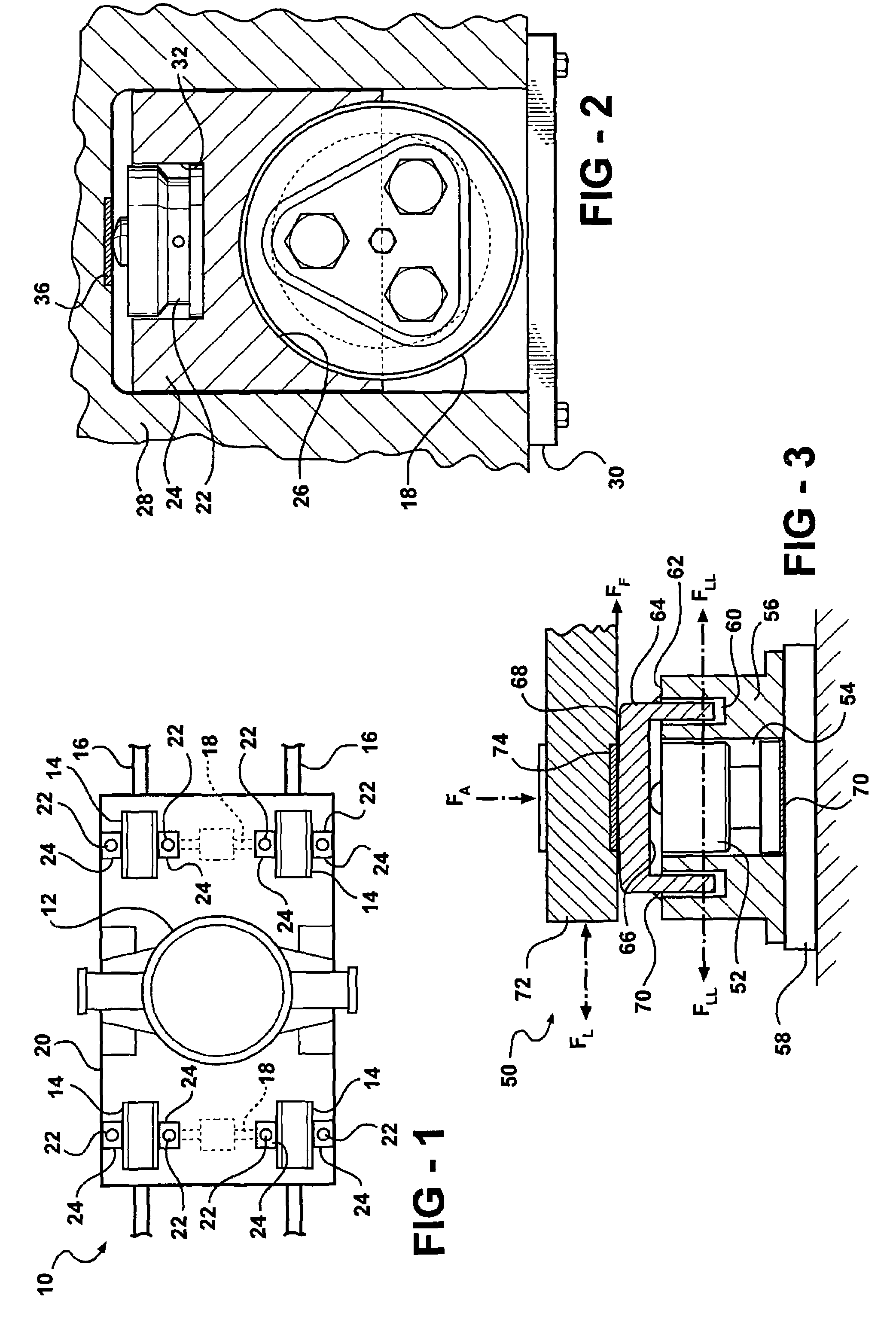
[0027]FIG. 1 depicts a railroad car 10. The railroad car 10 shown is commonly used in steel mills and includes a ladle 12 disposed thereon for holding molten steel therein. The wheels 14 of the railroad car 10 are adapted to ride on track rails 16. An axle 18 extends between each pair of wh...


PUM


Abstract

A load cell system for stationary or moving equipment is disclosed, wherein undesirable bending, shear, and torsion loads are minimized and an accuracy of the load cell system is maximized.

Description

FIELD OF THE INVENTION[0001]The invention relates to a load cell system and more particularly to a load cell system for stationary or moving equipment.BACKGROUND OF THE INVENTION[0002]In typical industrial settings, it is often desirable to obtain a weight of a raw or finished material. It has been a common practice to use load cells for determining this weight. Often, the materials are stored in tanks, hoppers, vehicles, or other containers, for example. One method used to obtain the weight of such containers is to provide a scale built into a floor or other supporting surface. The container is then positioned on the scale to determine the weight thereof.[0003]Another method which is commonly used on moving containers such as cars, railroad cars, and other vehicles is to provide an undercarriage platform and a separate load holding platform which supports the transported load. Load cells are typically placed between the platforms. This system requires elaborate and expensive auxili...

Claims


Application Information

Patent Timeline
Patent Type & Authority Patents(United States)
IPC IPC(8): G01G21/02
CPCG01G21/23Y10S177/09
Inventor SIKULA, FRANK
Owner ELECTRIC ARC TECH
Why Eureka
Try Eureka