Heat dissipating device having a fin also functioning as a fan duct

a heat dissipating device and fan duct technology, which is applied in the direction of air heaters, indirect heat exchangers, lighting and heating apparatus, etc., can solve the problems of motherboard life shortening and CPU not working normally

Active Publication Date: 2007-05-08
CHAMP TECH OPTICAL FOSHAN
View PDF18 Cites 106 Cited by
  • Summary
  • Abstract
  • Description
  • Claims
  • Application Information

AI Technical Summary

Problems solved by technology

Excessively high temperature causes the CPU unable to work normally.
The MOSFET delivers the heat to the motherboard and causes temperature of the motherboard to increase quickly, thus shortening a life span of the motherboard.
Regardless of the mounting positions of the fans, the two heat dissipating devices only dissipate the heat generated by the CPUs, but can not dissipate the heat generated by the MOSFETs beside the CPUs because the airflows generated by the fans are not guided to blow the MOSFETs.

Method used


Image

  • Heat dissipating device having a fin also functioning as a fan duct
  • Heat dissipating device having a fin also functioning as a fan duct
  • Heat dissipating device having a fin also functioning as a fan duct

Examples


Embodiment Construction

[0010]Reference will now be made to the drawing figures to describe a heat dissipating device having a fin functioning as a fan duct in accordance with a preferred embodiment of the present invention in details.

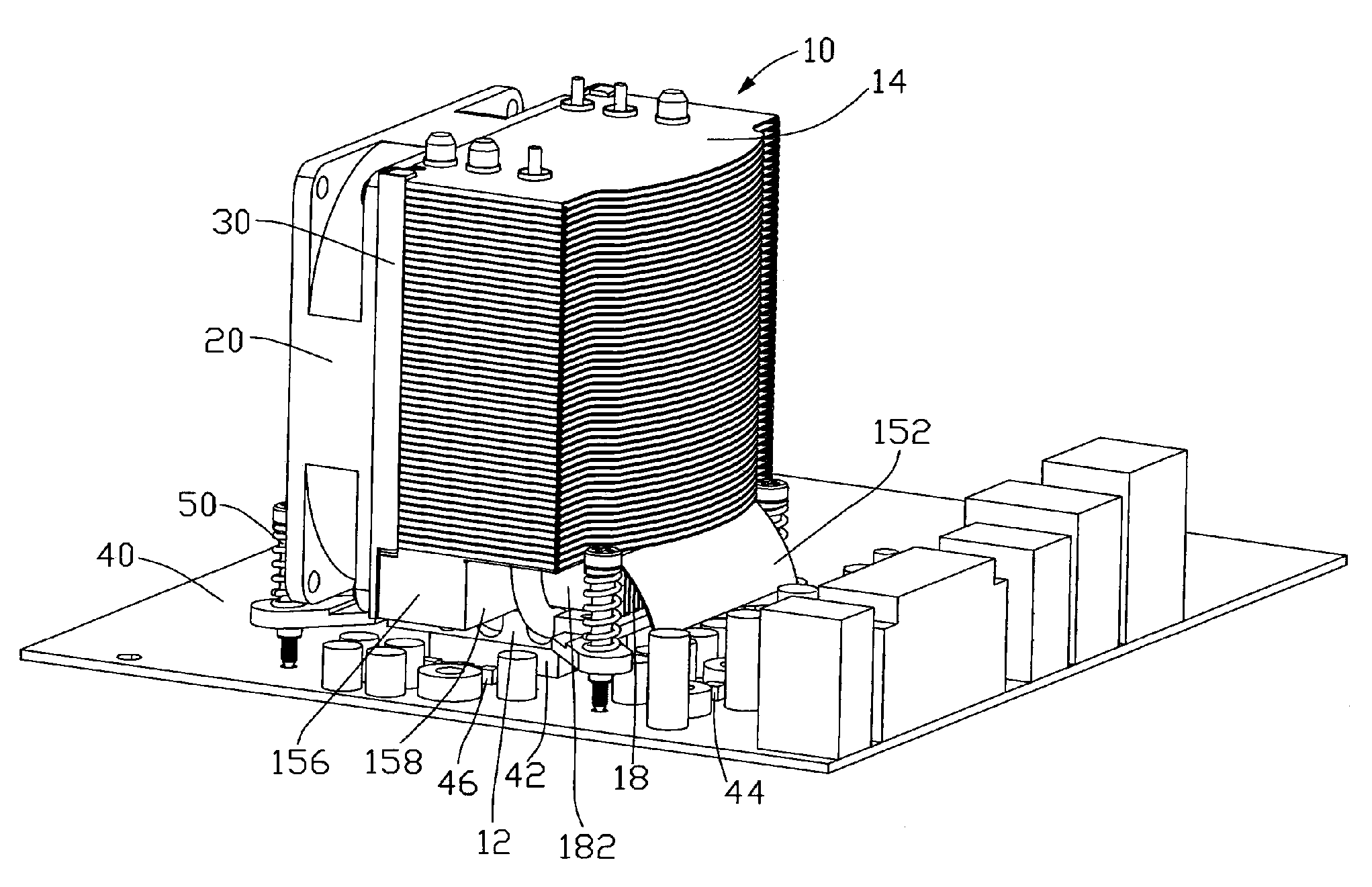
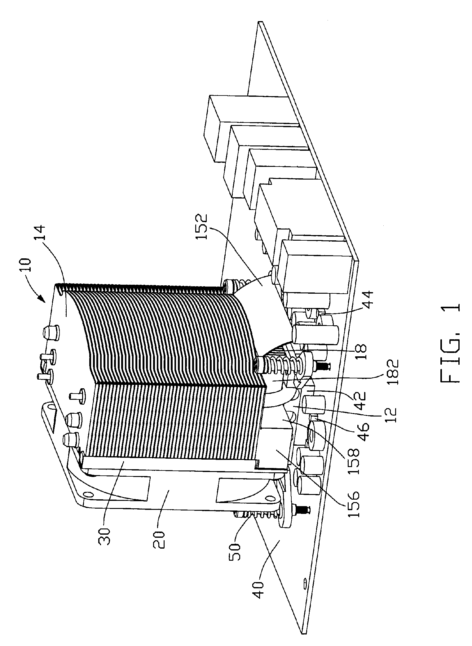
[0011]FIG. 1 shows a heat dissipating device mounted on a printed circuit board 40 (PCB) comprising a heat sink assembly 10 and a fan 20 mounted to a front side of the heat sink assembly 10 via a pair of fan holders 30.

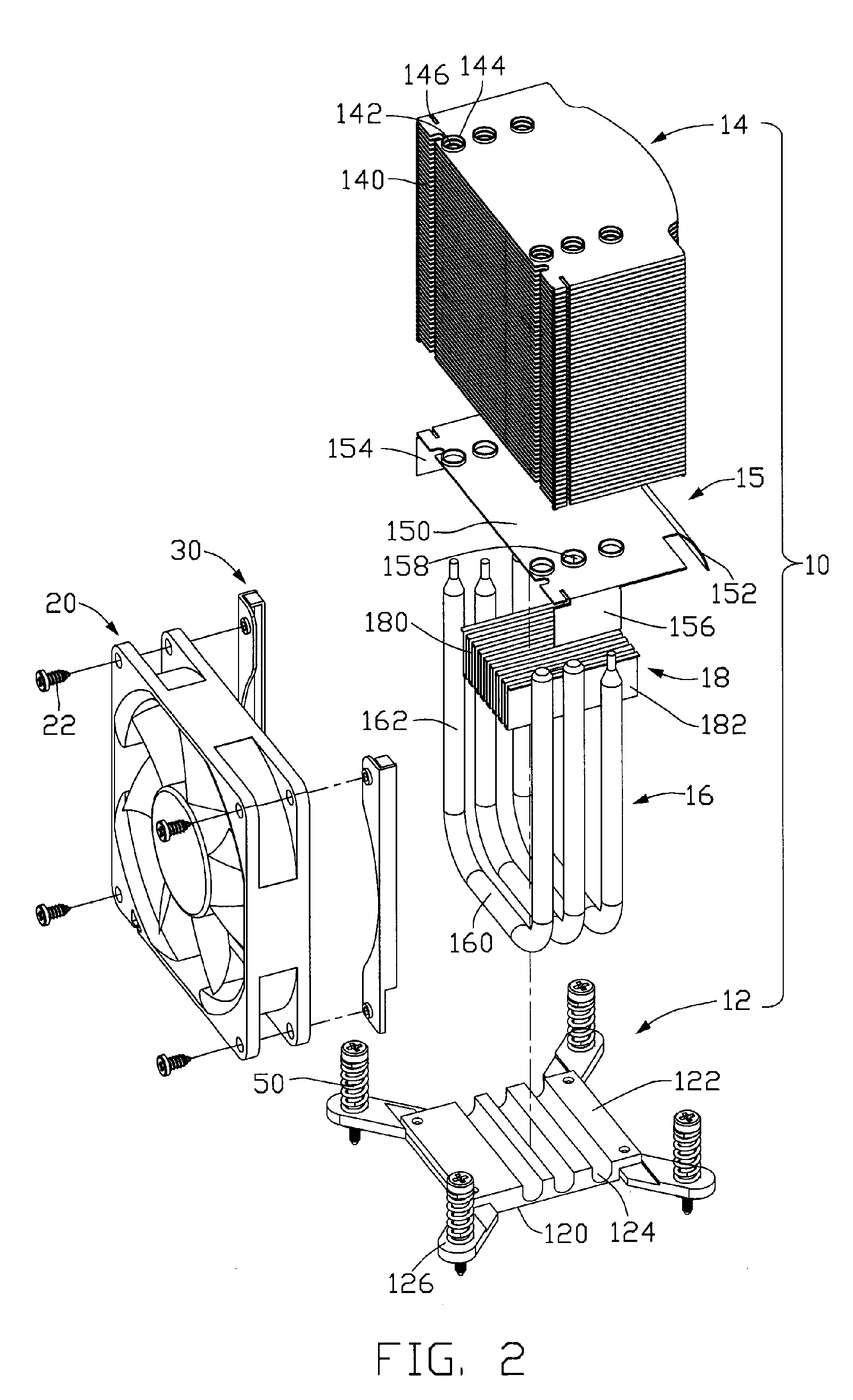
[0012]Also referring to FIG. 2, the heat sink assembly 10 comprises a heat spreader 12, a plurality of first and second fins 14, 18, three parallel U-shaped heat pipes 16 thermally connecting the heat spreader 12 and the first and second fins 14, 18.

[0013]The heat spreader 12 has a bottom face 120 for contacting a CPU 42 mounted on the PCB 40 to absorb heat therefrom, and a top face 122 with three grooves 124 receiving evaporating portions 160 of the heat pipes 16. The heat spreader 12 forms four ears 126 extending outwardly from four corners of the heat spread...


PUM


Abstract

A heat dissipating device for cooling a number of electronic devices, includes a heat sink assembly (10) and a fan (20) mounted to a side of the heat sink assembly. The heat sink assembly includes a heat spreader (12), a plurality of fins (14), and heat pipes thermally connecting the heat spreader and the fins. The fins form a plurality of channels (140) therebetween, and include a guiding fin (15). The guiding fin includes a body (150) spaced from the heat spreader and an inclined sidewall (152) bent from the body. An airflow generated by the fan has a portion flowing through the channels of the fins and another portion flowing between the body and the heat spreader for blowing a second heat generating electronic device by guiding of the sidewall of the guiding fin.

Description

FIELD OF THE INVENTION[0001]The present invention relates to a heat dissipating device having a plurality of fins, wherein one of the fins also functions as a fan duct to guide an airflow flowing from a fan to electronic devices in a computer system.DESCRIPTION OF RELATED ART[0002]A central processing unit (CPU) mounted on a motherboard in a computer is an operation center of the computer. During operation of the computer, the CPU produces heat. The heat must be quickly carried away from the CPU during the operation of the computer. Excessively high temperature causes the CPU unable to work normally. Various cooling devices have been developed for dissipating the heat from the CPU of the computer. However, except the CPU, a MOSFET (Metal Oxide Semiconductor Field Effect Transistor) near to the CPU is also a source of heat that needs to be cooled. The MOSFET on the motherboard regulates and provides power for the CPU. The MOSFET delivers the heat to the motherboard and causes tempera...

Claims


Application Information

Patent Timeline
Patent Type & Authority Patents(United States)
IPC IPC(8): H05K7/20
CPCH01L23/427H01L23/467H01L2924/0002H01L2924/00F28D15/0275
Inventor WU, YI-QIANGCHEN, CHUN-CHI
Owner CHAMP TECH OPTICAL FOSHAN
Why Eureka
Try Eureka