Demodulator for an amplitude-modulated alternating signal

Active Publication Date: 2007-05-08
STMICROELECTRONICS SRL
View PDF4 Cites 13 Cited by
  • Summary
  • Abstract
  • Description
  • Claims
  • Application Information

AI Technical Summary

Benefits of technology

[0042]The demodulator according to the invention allows to frame very precisely the start and end of modulation. It

Problems solved by technology

The greater is the range, and the more the device is stealthy, the more the demodulation shall be subject to error.
Such a demodulation device presents a number of limitations due to its very structure.
This situation makes it difficult to generate a reliable comparison level on a permanent basis.
This probl

Method used


Image

  • Demodulator for an amplitude-modulated alternating signal
  • Demodulator for an amplitude-modulated alternating signal
  • Demodulator for an amplitude-modulated alternating signal

Examples


Embodiment Construction

[0057]The description that follows makes reference to a contactless card receiving from the reader an amplitude modulated signal whose carrier frequency is 13.56 MHz and whose modulation index is 10%. The application requires an RF communication range capable of attaining 1 m for a card displacement speed in the field of the reader that can attain 3 m / s.

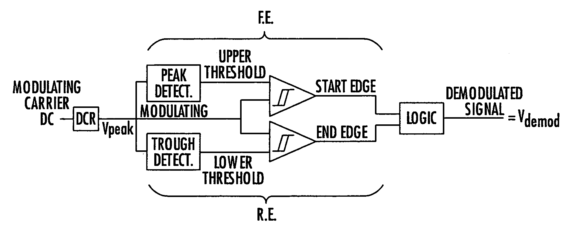
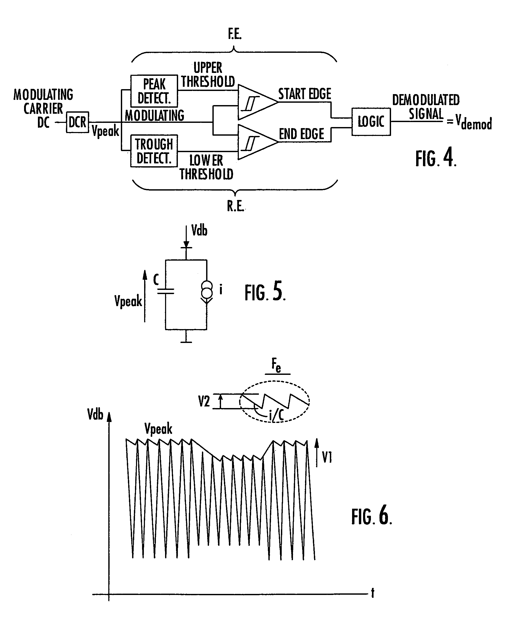
[0058]Referring to FIG. 4, which is a block diagram of the demodulator according to the invention, the modulated signal Vdb is first of all processed by a “peak detection ” cell DCR, which extracts the reference modulating signal Vpeak.

[0059]Two independent demodulators FE and RE arranged in parallel then detect respectively the start and end of the modulation, these intermediate results are then digitally processed by logic to produce the demodulated signal.

[0060]The first demodulator shall hereafter be designated “Falling Edge” FE, since it detects the upper threshold of the reference modulating signal Vpeak and identifies the star...


PUM


Abstract

The invention concerns a demodulator of an amplitude-modulated signal (Vdb), characterised in that it comprises a peak detecting cell (DCR) capable of extracting the reference modulating signal (Vpeak1) of the modulated signal (Vdb); a first demodulator (FE) adapted to detect the peak of the reference modulating signal (Vpeak1) to generate a high comparison threshold and locate the start of the modulation, a second demodulator (RE) adapted to detect a trough of the reference modulating signal (Vpeak1) to generate a low comparison threshold and locate the end of the modulation; a logic processing unit capable of supplying the demodulated signal (Vdemod).

Description

FIELD OF THE INVENTION[0001]The present invention relates to a demodulator for an amplitude modulated alternating signal based on the peak and trough detection principle. The invention also relates to a contactless device comprising such a demodulator.[0002]The demodulator according to the invention has a particularly advantageous application in the field of long range radio frequency (RF) communication.BACKGROUND OF THE INVENTION[0003]Contactless communication portable devices such as contactless IC (integrated circuit) cards (also known as chip cards or smart cards), electronic labels or tags, or badges, operate on the basis of a communication by an electromagnetic field with a read and / or write interrogating device, generically referred to as a reader. Such contactless devices generally comprise a microcircuit connected to a parallel LC type resonant circuit. The inductor is an external antenna, while the capacitor is integrated to the microcircuit. The two form what is commonly ...

Claims


Application Information

Patent Timeline
IPC IPC(8): H04L27/00H03D1/00G06K7/00G06K19/07H03D1/10H03K5/08H04L25/03H04L25/06H04L27/06
CPCG06K7/0008G06K19/0701G06K19/0723H03D1/10H03K5/082H04L25/061
Inventor RIZZO, PIERREDELL'OVA, FRANCIS
Owner STMICROELECTRONICS SRL
Why Eureka
Try Eureka