Guidance of an optical scanning device

a scanning head and optical technology, applied in the direction of magnetic recording, data recording, instruments, etc., can solve the problem of inability to prevent the relative movement of the scanning head, and achieve the effect of eliminating the fit toleran

Inactive Publication Date: 2007-05-08
ROBERT BOSCH GMBH
View PDF18 Cites 7 Cited by
  • Summary
  • Abstract
  • Description
  • Claims
  • Application Information

AI Technical Summary

Benefits of technology

[0014]An object of the present invention is generally to eliminate the fit tolerance between the scanning head or the bearing device attached to it and its guide device.
[0017]In contrast to the known approaches, the optical scanning device of the present invention has the advantage that the scanning head is guided reliably and free from play even in the presence of vibrations and consequently the resistance to shock is increased. Using the invention makes it possible to reduce the vibration sensitivity of optical data scanning devices. This thus eliminates a weakness of many scanning devices available on the market and increases the selection of possible types for vibration-relevant uses.
[0021]According to another preferred enhancement, the bearing device is made up of a bearing shell to accommodate the guide device and of an elastic matrix element coupled to the scanning head. The elasticity of the matrix element makes it possible to apply a force of a predefined magnitude and direction to the guide device.
[0022]According to another preferred enhancement, the matrix element has a plurality of teeth which engage the grooves of the guide device to convert the rotational movement of the guide device into a linear movement of the scanning head. The sizes of the grooves and the corresponding teeth are matched to ensure good guidance. This makes it possible to control the movement of the scanning head on the predefined radial track using the motor.
[0023]According to another preferred enhancement, the prestressing device is embodied as a spring element, as a leaf spring in particular, which may be attached to the elastic matrix element in such a manner that it is possible to press the plurality of teeth using a static prestress of a predefined magnitude and direction against the guide device. This eliminates the play between the guide device and the bearing device.
[0025]According to another preferred enhancement, the prestressing device is embodied as an additional spring element which is attached in the at least one bearing device connected to the scanning head for applying a static prestress of a predefined magnitude and direction to the at least one guide device in order to prestress it and the bearing device against each other. This offers the advantage that it is only necessary to modify already existing parts slightly for improved resistance to shock in conventional drives. This type of tolerance fit elimination is thus a cost-effective means to achieve the objective.

Problems solved by technology

In practice, requirements with regard to robustness (e.g., sensitivity to temperature and moisture variations, contaminations), service life, production capabilities, production tolerances and production costs place such narrow limits on these methods that it is impossible to prevent a relative movement of the scanning head at even low vibration.

Method used


Image

  • Guidance of an optical scanning device
  • Guidance of an optical scanning device
  • Guidance of an optical scanning device

Examples


Embodiment Construction

[0034]In the figures, identical reference symbols denote identical components or those having identical functions.

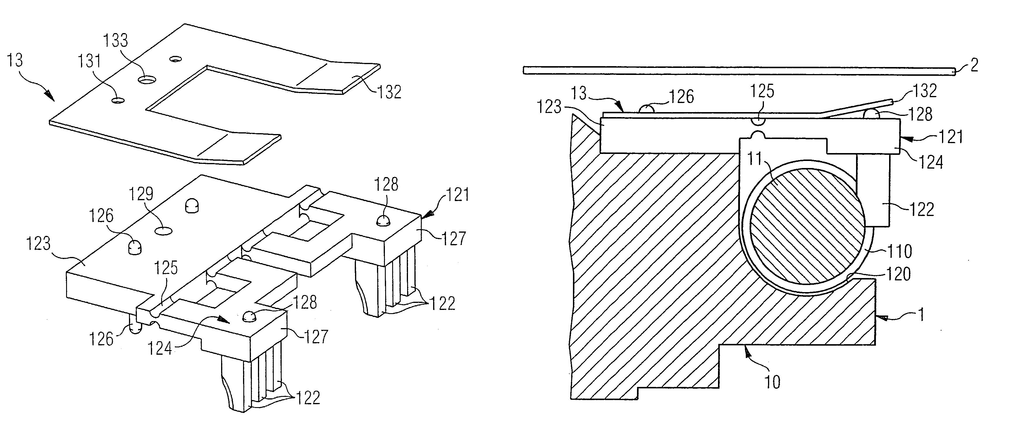
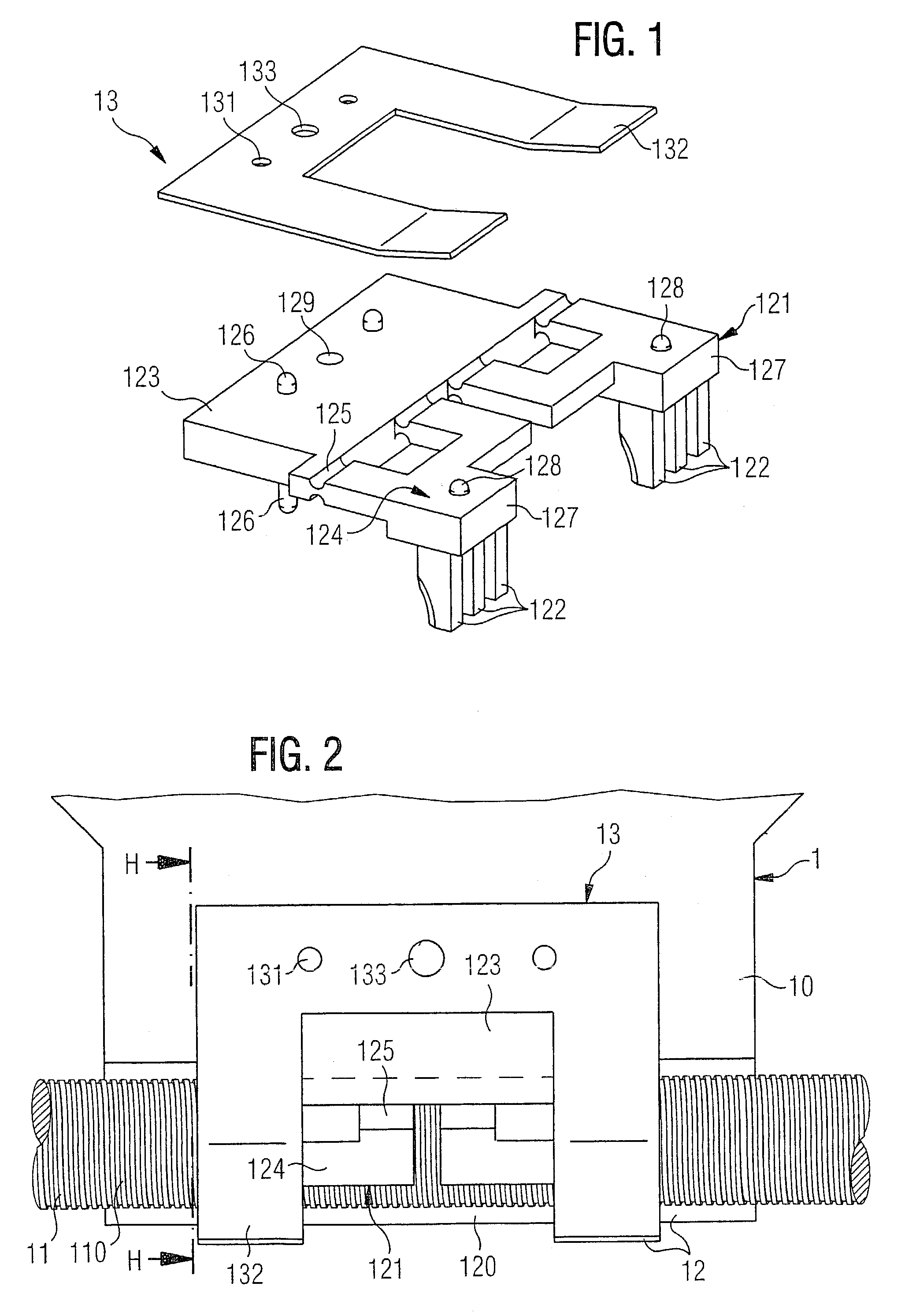
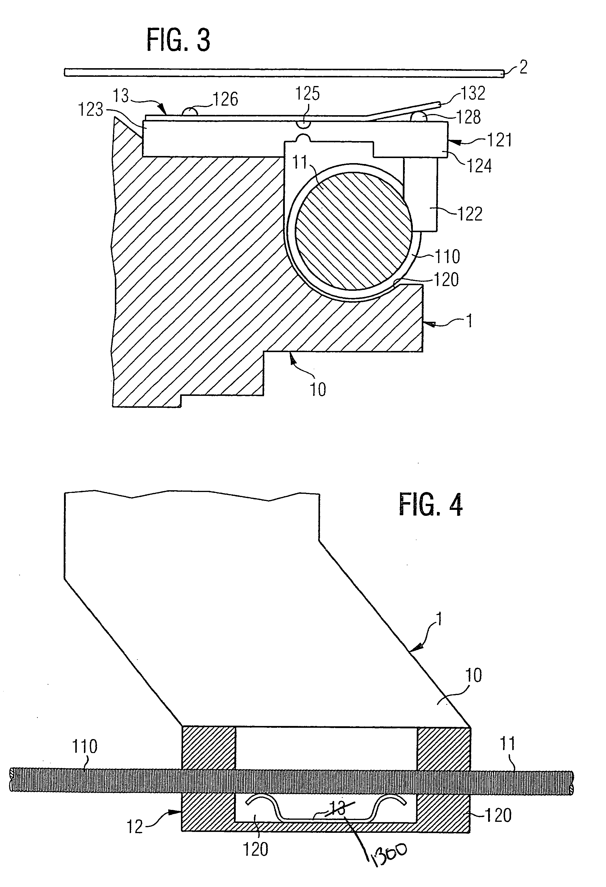
[0035]FIG. 1 shows a perspective view of an elastic matrix element 121 which is embodied as a part of a bearing device 12 to accommodate a guide device 11 shown in FIG. 2 and a correspondingly embodied prestressing device 13 in the form of a leaf spring 13 according to a first exemplary embodiment of the present invention.

[0036]Matrix element 121 is made of a back section 123, which may be affixed to scanning head 10, and a front section 124, which is elastically connected to back section 123, both the top and bottom of connection point 125 between back section 123 and front section 124 being formed in the shape of a channel and thus being used as a hinge for an elastic movement. Due to the recess at connection point 125, the stiffness is reduced there compared to the back and front section and connection point 125 acts as a hinge when force is applied to front section 1...


PUM

PropertyMeasurementUnit
frequencyaaaaaaaaaa
elasticaaaaaaaaaa
elastic matrixaaaaaaaaaa

Abstract

An optical scanning device for reading data stored on a rotating recording medium having a scanning head; at least one guide device for guiding the scanning head along a predefined track; at least one bearing device connected to the scanning head for supporting the at least one guide device and having at least one elastic prestressing device to provide a static prestress on the at least one guide device to prestress the same and the at least one bearing device connected to the scanning head against each other to eliminate a relative displacement.

Description

FIELD OF THE INVENTION[0001]The present invention relates to an optical scanning device for reading stored data on a rotating recording medium, in particular a scanning device having a scanning head, at least one guide device for guiding the scanning head along a predefined track and at least one bearing device connected to the scanning head for supporting the at least one guide device.BACKGROUND INFORMATION[0002]An optical scanning head of a scanning device is guided along a data track to read data stored on a rotating recording medium.[0003]The scanning head directs a light beam onto the rotating recording medium through a lens attached to the scanning head to acquire the recorded information by scanning the data tracks applied to the recording medium. In order to avoid data reading errors, it is important in particular that the light beam is always guided exactly along the data tracks and is focused on the recording medium.[0004]The housing of, e.g., a compact disc (CD) drive ins...

Claims


Application Information

Patent Timeline
Patent Type & Authority Patents(United States)
IPC IPC(8): G11B7/085G11B19/20G11B21/02
CPCG11B7/08582
Inventor HERMANNS, INGO
Owner ROBERT BOSCH GMBH
Why Eureka
Try Eureka