
Hospital bed and mattress having a retractable foot section

a foot section and bed frame technology, applied in the field of adjustable beds, can solve the problems of increasing the risk of skin failure on other areas of the foot and body, confined individuals, and vulnerable to skin breakdown on the back of the heel, so as to reduce or eliminate reduce or eliminate pressure and shear, and reduce the effect of reducing or eliminating the time an individual spends

Inactive Publication Date: 2007-05-15
HILL ROM SERVICES
View PDF127 Cites 48 Cited by
  • Summary
  • Abstract
  • Description
  • Claims
  • Application Information

AI Technical Summary

Benefits of technology

The system effectively reduces patient migration, customizes bed size to the patient, and minimizes heel pressure, improving patient security and comfort while reducing the need for additional components and caregiver time.

Problems solved by technology

Certain individuals who are confined to bed for an extended period of time are vulnerable to skin breakdown on the back of the heel.
Reducing or eliminating the time an individual spends in a supine position will protect the heel area, although it may increase the risk of skin failure on other areas of the foot and body.
Components which are removed from the bed have the potential to get lost or mislaid.
Components that are added to the bed provide an extra cost associated with the purchasing, cleaning, and disposal of the added components.
There is also a cost in time for the caregiver who must go through multiple steps to initiate and maintain the support of the device.

Method used


Image

  • Hospital bed and mattress having a retractable foot section
  • Hospital bed and mattress having a retractable foot section
  • Hospital bed and mattress having a retractable foot section

Examples


Embodiment Construction

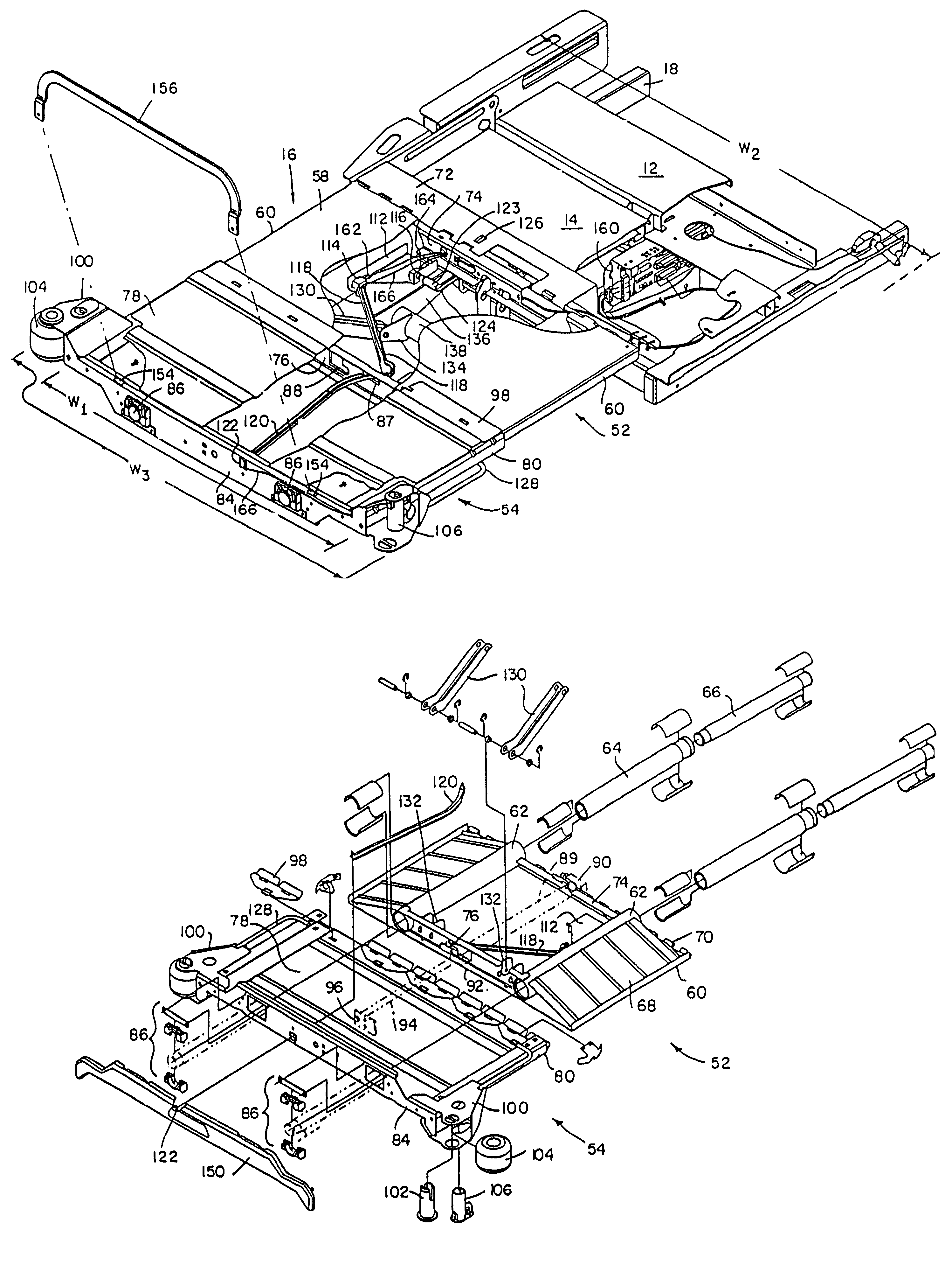
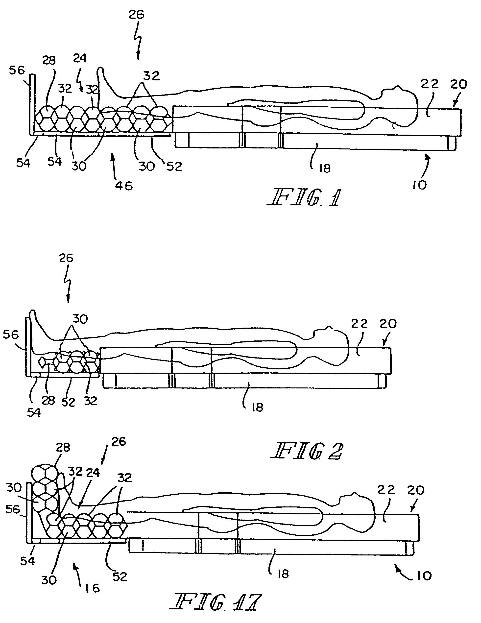
[0037]As illustrated in the Figures, the bed will be discussed with respect to a deck 10 and a mattress 20 thereon. As illustrated in FIG. 4, the deck 10 includes a seat section 12, a thigh section 14 and a foot section 16 mounted to a frame 18. The deck would also include, but not shown, a head section also connected to the frame 18. Since the present disclosure is directed specifically to the foot section 16, the other portion will not be described in detail. The foot portion 16 may be used on any deck structure.

[0038]The retracting foot section of the present disclosure can be retracted while the bed is in its horizontal bed position. This permits the caregiver to adjust the overall length of the bed in either the bed position or the chair position as shown in FIGS. 19 and 20. The overall bed length can be shortened by about 12–14 inches to facilitate transport of the bed. In other words, the retracting foot section reduces the bed length so that the bed can fit into smaller elev...


PUM


Abstract

A patient support is disclosed having an adjustable length deck and a mattress positionable on the deck.

Description

[0001]This is a continuation of U.S. patent application Ser. No. 10 / 770,721, filed Feb. 3, 2004 now U.S Pat. No. 7,000,272, which is a continuation of U.S. patent application Ser. No. 09 / 755,583, filed Jan. 5, 2001, now U.S. Pat. No. 6,496,993, which is a divisional of U.S. patent application Ser. No. 09 / 120,125, filed Jul. 22, 1998, now U.S. Pat. No. 6,212,714, which is a continuation-in-part of U.S. patent application Ser. No. 08 / 901,840, filed Jul. 28, 1997, now U.S. Pat. No. 6,151,739, which is a continuation of U.S. patent application Ser. No. 08 / 367,829, filed Jan. 3, 1995, now U.S. Pat. No. 5,666,681; a continuation-in-part of U.S. patent application Ser. No. 09 / 018,542, filed Feb. 4, 1998, now U.S. Pat. No. 6,163,903; and a divisional of U.S. patent application Ser. No. 08 / 511,711 filed Aug. 4, 1995, now U.S. Pat. No. 5,715,548 and claims benefit of U.S. Provisional Patent Application No. 60 / 059,772, filed Sep. 23, 1997 with respect to common subject matter. The disclosures ...

Claims


Application Information

Patent Timeline
Patent Type & Authority Patents(United States)
IPC IPC(8): A61G7/10A47C19/04A47C21/08A47C27/10A61G5/00A61G7/00A61G7/002A61G7/005A61G7/008A61G7/012A61G7/015A61G7/018A61G7/05A61G7/053A61G7/057A61G7/075A61G7/16
CPCA61G7/00A61G7/008A61G7/015A61G7/018A61G7/0507A61G7/053A61G7/0755A61G7/16A61G7/002A61G2203/726A61G7/005A61G7/012A61G7/05769A61G2007/0509A61G2007/051A61G2007/0514A61G2007/0519A61G2007/0527A61G2203/34A61G2203/74A61G2203/42A61G7/0509A61G7/051A61G7/0514A61G7/0519A61G7/0527
Inventor ALLEN, E. DAVIDKRAMER, KENNETH L.WUKUSICK, PETER M.MEYER, ERIC R.BRANSON, GREGORY W.ULRICH, DAVID J.THOMAS, JAMES M. C.MCDANIEL, III, PAUL M.ZWINK, DENNIS R.
Owner HILL ROM SERVICES
Learn More