Wood burning stove having pivoting baffle and method

a wood burning stove and pivoting technology, applied in the field of wood burning stoves, can solve the problems of affecting the loading of wood into the stove, affecting the efficiency of the stove, and the cost of the catalytic combustible, so as to achieve optimal air flow patterns within the stove

Inactive Publication Date: 2007-05-15
HEARTH & HOME TECH
View PDF39 Cites 11 Cited by
  • Summary
  • Abstract
  • Description
  • Claims
  • Application Information

AI Technical Summary

Benefits of technology

[0007]The present disclosure provides a stove, in particular, a wood burning stove, that has a baffle assembly disposed within to provide optimal air flow patterns within the stove. A portion of the baffle assembly is pivotable to provide easy access to the combustion chamber to allow loading of fuel into the stove.
[0008]In particular, the stove includes a stove body which defines a stove exterior, a stove interior, and a combustion chamber disposed within the interior. A baffle plate is disposed within the combustion chamber, the baffle plate being moveable from a “closed” configuration to an “open” configuration. When in the “closed” configuration, the baffle plate is positioned substantially horizontally and is spaced apart from at least a portion of at least one wall. When in the “open” configuration, the baffle plate is positioned substantially vertically such that a by-pass pathway is created between a top access door and the combustion chamber. This allows for easy top-loading of fuel.

Problems solved by technology

With this extended burning of wood as the primary fuel comes the challenge of providing an efficient stove that meets the Environmental Protection Agency requirements and state agency requirements for emissions, including particulate material and gases.
However, the catalytic combustors can become fouled or otherwise rendered inefficient, especially when other than selected materials are burned within the stove.
Additionally, the catalytic combustors are quite expensive and must be periodically replaced.
Depending on the design of the various channels or baffles, loading of wood into the stove can be hampered.
If the stove is a top-loading stove, that is, where wood can be inserted into the combustion chamber through the top surface of the stove, such baffles hinder access to the combustion chamber.

Method used


Image

  • Wood burning stove having pivoting baffle and method
  • Wood burning stove having pivoting baffle and method
  • Wood burning stove having pivoting baffle and method

Examples


first embodiment

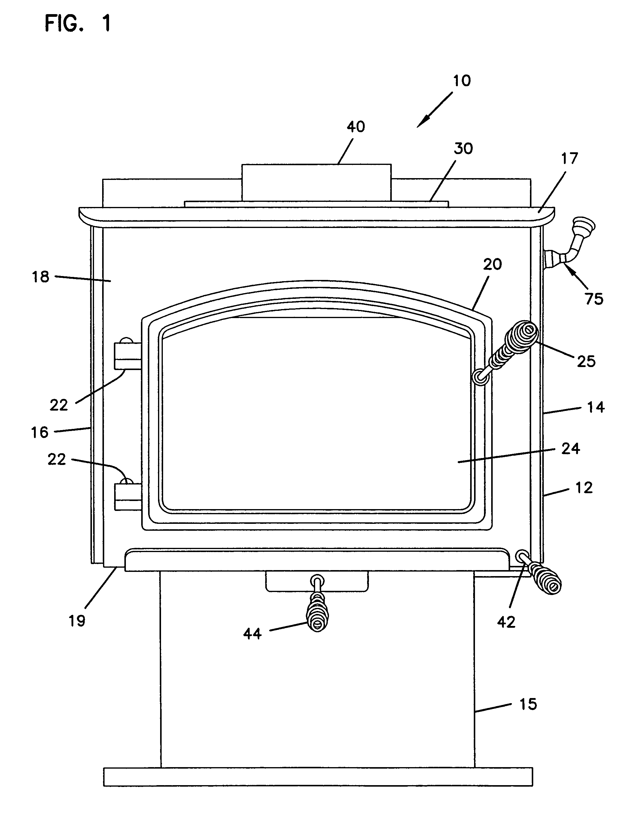
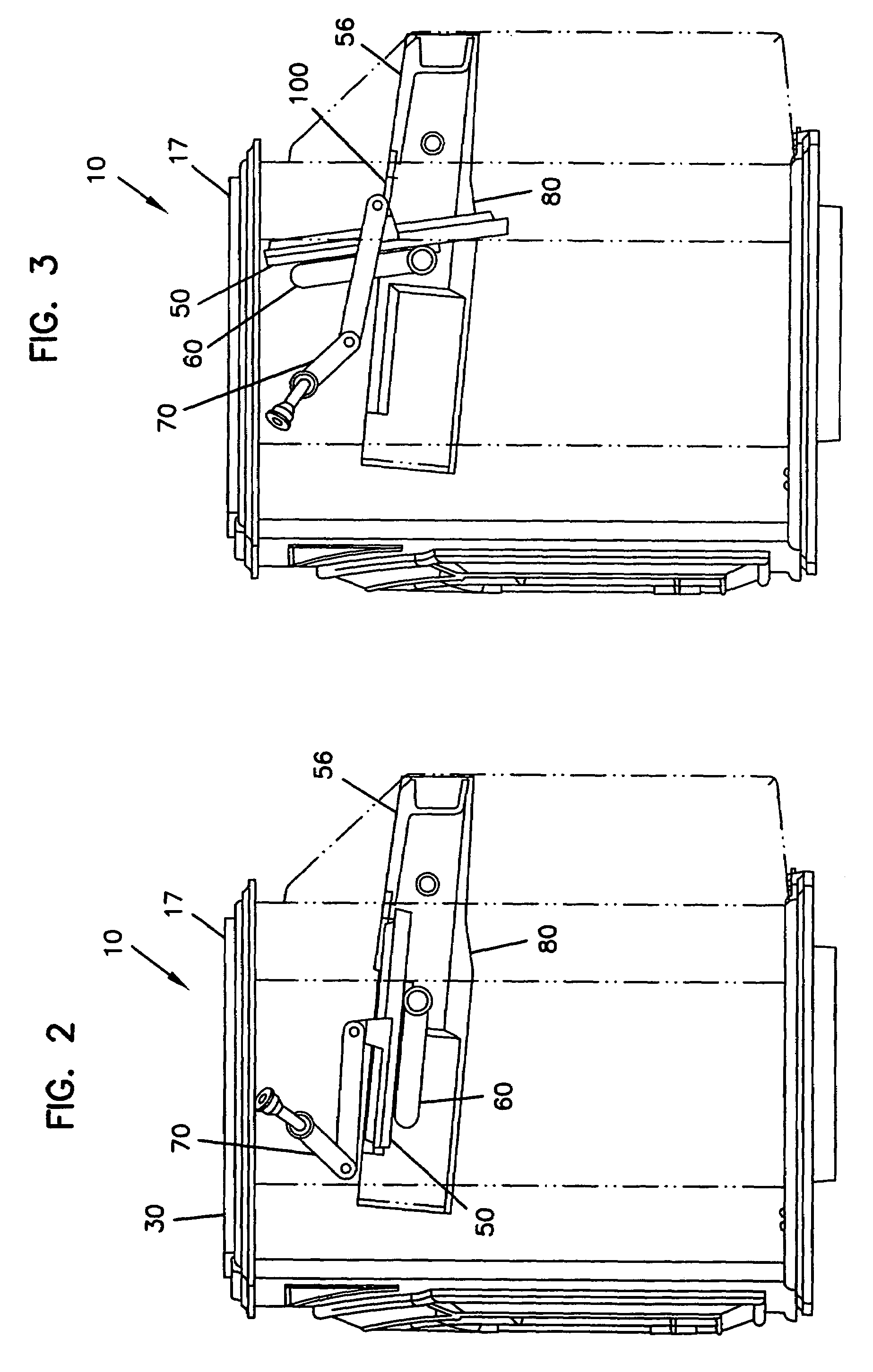
[0038]FIGS. 4 through 7 show various elements of the baffle assembly. In FIG. 4, the various elements are shown in exploded view; in FIGS. 5 through 7, a portion of the baffle assembly is shown. In particular, in accordance with the present disclosure and shown in each of FIGS. 4 through 7, a moveable baffle plate 50 is provided. Baffle plate 50 has a generally planar, solid face 52. Various strengthening features, such as ribs and the like, may be included in or on baffle plate 50. A fixed baffle plate 56, shown in FIG. 4, is also provided in the baffle assembly. Fixed baffle plate 56 is fixed to the combustion chamber side of the back wall of the stove 10. Baffle plates 50, 56 are typically made from a sheet of metal, such as steel or cast iron, although other materials, such as ceramic materials, can be used.

[0039]Disposed proximate to baffle plate 50 is an air manifold 60 for providing and further manipulating air flow within the combustion chamber. The air manifold creates a se...

second embodiment

[0046]FIGS. 14 through 18 show various elements of the baffle assembly, in which the air manifold is expanded. In FIG. 18, the various elements are shown in exploded view; in FIGS. 14 through 17, a portion of the baffle assembly is shown. In particular, in accordance with the present disclosure and shown in each of FIGS. 14 through 18, a moveable baffle plate 150 is provided. Baffle plate 150 has a generally planar, solid face 152. Various strengthening features, such as ribs and the like, may be included in or on baffle plate 150. A fixed baffle plate 156, shown in FIG. 18, is also provided in the baffle assembly. As shown in FIG. 18, fixed baffle plate 156 is fixed to the combustion chamber side of the back and / or side walls of the stove 10 via rear mounting member 204. It is to be understood that fixed baffle plate 156 can alternatively be fixed to the rear portion of the mounting members 180. Baffle plates 150, 156 are typically made from a sheet of metal, such as steel or cast ...


PUM


Abstract

A wood burning stove is provided. The combustion chamber in which the fire occurs has a baffle plate that is moveable to direct air flow through one of two different pathways from the combustion chamber to the chimney. When in a first position, the baffle plate forces the air and smoke to move through a first pathway; when in a second position, a by-pass pathway is opened, allowing air and smoke to move through a second pathway. The stove can have a door in the front wall, or the top wall, or both walls, to provide access to the combustion chamber.

Description

[0001]This application is a continuation of application Ser. No. 09 / 809,627, filed Mar. 15, 2001, now U.S. Pat. No. 6,688,302 , which claims the benefit of U.S. Patent Provisional Application Ser. No. 60 / 189,561, filed Mar. 15, 2000, which applications are incorporated herein by reference.FIELD OF THE DISCLOSURE[0002]This disclosure relates generally to wood burning stoves. In particular, this disclosure relates to wood burning stoves having a baffle for regulation of air flow within the stove, and methods of using the stove.BACKGROUND OF THE DISCLOSURE[0003]Whether for providing heat, for purely decorative purposes, or for value enhancement, wood burning stoves have become commonplace in today's building trades for both residential and commercial applications for situations where a fireplace is not feasible or desired. In some instances, wood burning stoves have been inserted into fireplace boxes. Stoves are often preferred over open fireplaces because many wood stoves have the cap...

Claims


Application Information

Patent Timeline
Patent Type & Authority Patents(United States)
IPC IPC(8): F24B1/00F24B1/189F24B5/02F24B5/00
CPCF24B1/1895F24B5/028
Inventor HENRY, DANIEL S.OWINGS, MATTHEWWEAVER, MONTE JAYWALLACE, BRIAN L.
Owner HEARTH & HOME TECH
Why Eureka
Try Eureka