Apparatus and method for reducing operating stress in a turbine blade and the like

a technology of operating stress and turbine blades, applied in the field of minimizing operating stress in the turbine blade, can solve the problems of fracture of solid parts of the casting core if not supported, and achieve the effect of minimizing operating mechanical stress

Active Publication Date: 2007-05-15
RTX CORP
View PDF25 Cites 32 Cited by
  • Summary
  • Abstract
  • Description
  • Claims
  • Application Information

AI Technical Summary

Benefits of technology

[0006]In accordance with one aspect of the present disclosure, a core for casting a metal part is provided. The core includes a body having solid portions spaced apart by hollow portions. The body also includes at least one support element extending between adjacent solid portions. The support element has a shape optimized to prevent the core from fracturing during the casting process and designed to minimize operating mechanical stress in the metal part formed by the support element.
[0007]In accordance with another aspect of the present disclosure, a method for designing a casting core is provided. The method defines a cross section for a support element by defining a first radius with a center point and a circumferential arc. Next, a second radius is defined with a center point and a circumferential arc positioned a first distance from the first center point. A third radius is defined by a center point and a circumferential arc positioned a second distance from the center point of the second radius. The design method further defines a fourth radius having a center point and circumferential arc positioned tangent to the circumferential arcs of the first, second, and third radii. A fifth radius having circumferential arcs positioned tangent to the circumference of the first, second and third radii and opposite of the fourth arc is also defined. The method produces a core support feature that adequately supports the core during the casting process and minimizes stress in the cast part.
[0008]In accordance with another aspect of the disclosure, a method for manufacturing a casting core is provided. The method includes providing ceramic slurry for delivery into a core die and forming a green core. The green core includes solid portions spaced apart by corresponding hollow portions. At least one support element is formed between adjacent solid portions of the core. The casting core is removed from the die and allowed to dry and then heated to a predetermined temperature to increase the material strength. The support elements are formed by defining a first radius, and a second radius a first distance from the first radius. A third radius is positioned a second distance from the second radius. A fourth radius having a circumference positioned tangent to the circumference of the first, second and third radii forms one side of a cross-section. A fifth radius having a circumference positioned tangent to the circumference of the first, second and third radii forms the opposite side of the cross section. The first and second radii can be substantially equal in length as can the fourth and fifth radii. The first and second distances can also be substantially equal in length.
[0010]In accordance with a still further aspect of the disclosure, a turbine blade can be manufactured according to the method described above to produce an air foil having solid portions with at least one through aperture formed therein by the casting core. The through aperture has a shaped optimized to minimize operating mechanical stress in a localized area around the aperture. The cast metal part is formed from a casting core that includes a body having solid portions spaced apart by hollow portions and at least one support element extending between adjacent solid portions that forms a through aperture in the cast metal part.

Problems solved by technology

The solid portions of the casting core will fracture if not supported adequately during the manufacturing process.

Method used


Image

  • Apparatus and method for reducing operating stress in a turbine blade and the like
  • Apparatus and method for reducing operating stress in a turbine blade and the like
  • Apparatus and method for reducing operating stress in a turbine blade and the like

Examples


Embodiment Construction

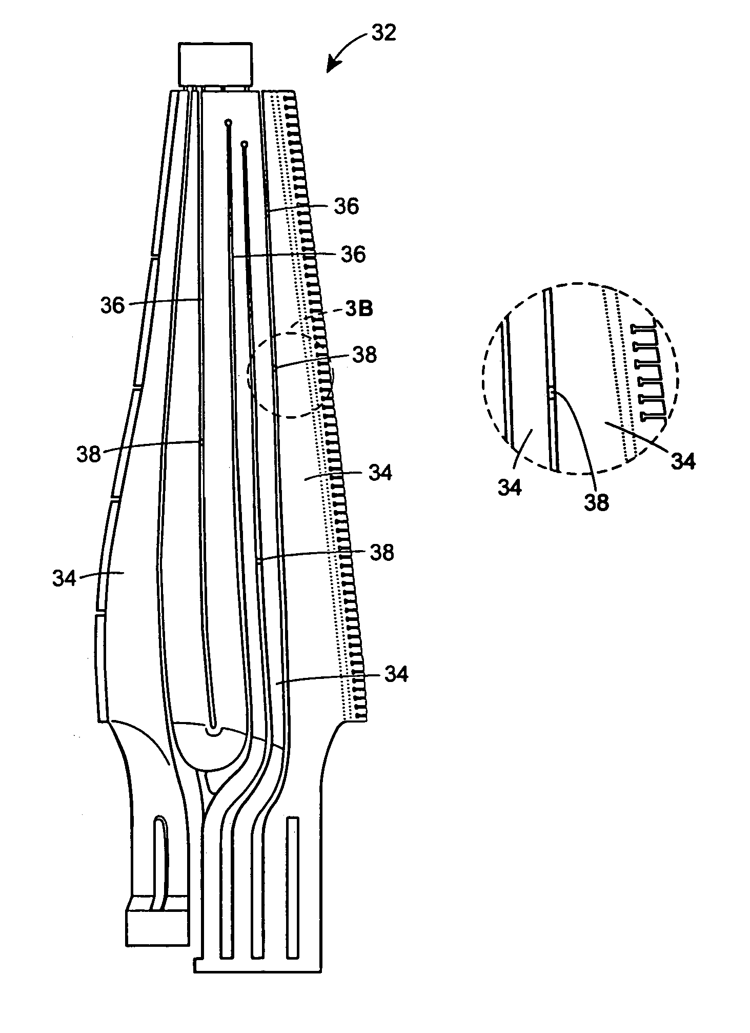
[0023]The present disclosure provides for an apparatus design and method for minimizing operating stress on parts manufactured by a casting process. In one embodiment of the present disclosure, the cast part is a turbine blade for a gas turbine engine, however, the cast part can be any of the type having complex internal geometry and subjected to high stresses during operation. The design and method can be used for both moving and static geometry.

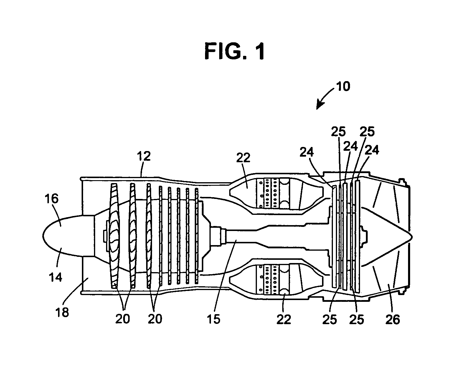
[0024]Referring now to FIG. 1, a cross-section of a typical gas turbine engine 10 is shown therein. The gas turbine engine 10 includes an outer case 12 to hold the internal turbo-machinery components and to attach the engine 10 to an aerospace vehicle (not shown). The gas turbine engine 10 includes a rotor 14 that includes a shaft 15 extending from the front of the engine to the rear of the engine. The casing 12 forms an inlet 18 in which air enters past a nosecone 16 and into the engine 10. The rotor can include an axial compressor 20 havi...


PUM

PropertyMeasurementUnit
stress levelsaaaaaaaaaa
mechanical stressaaaaaaaaaa
thicknessaaaaaaaaaa

Abstract

A core for casting a metal part having a body with solid portions spaced apart by hollow portions. The body includes at least one support element extending between adjacent solid portions. The support element provides stiffness and strength for the casting core during the casting process. The support element has an optimized shape to prevent the core from fracturing during the casting process and to minimize operating stress in the metal part around the area formed by the support element.

Description

GOVERNMENTS RIGHTS IN THE INVENTION[0001]The invention was made by or under contract with the Navy of the United States Government under contract number N00019-02-C-3003.FIELD OF THE DISCLOSURE[0002]The present disclosure generally relates to a method and apparatus for designing and manufacturing a cast part to minimize mechanical operating stress, and more particularly to minimizing operating stress in a turbine blade.BACKGROUND OF THE DISCLOSURE[0003]Component casting is typically used when large quantities of identical products are being produced or when design specifications require intricate internal geometry that machining apparatus such as mills, drill presses, and / or lathes cannot access. Highly stressed components such as turbine blades in gas turbine engines require casting techniques that minimize localized stress caused by internal geometric features. Turbine blades, and the like, have internal hollow portions to reduce the weight of the blade and provide passages for co...

Claims


Application Information

Patent Timeline
Patent Type & Authority Patents(United States)
IPC IPC(8): B22C9/00B22C9/10B22C9/04F01D5/08B22C9/24F01D9/02F01D25/00F02C7/00
CPCB22C9/04B22C9/10
Inventor OTERO, EDWINSTRONG, PATRICK
Owner RTX CORP
Why Eureka
Try Eureka