Led nail clipper

a nail clipper and nail technology, applied in the field of lighting devices, can solve the problems of injuring the animal, difficulty in clipping off the desired amount, and increased risk of injury to the animal

Inactive Publication Date: 2007-05-15
VRSALOVIC TATIANA +1
View PDF6 Cites 19 Cited by
  • Summary
  • Abstract
  • Description
  • Claims
  • Application Information

AI Technical Summary

Problems solved by technology

Many dogs object to nail cutting because someone has clipped their nails too short in the past and hurt them.
Often-times the animals squirm and move around making it difficult to clip off the desired amount.
When cut too short, it causes pain and bleeding thus injuring the animal.
Placing the nail too far into the blades will cause too much to be removed resulting in injury.
Conversely, placing too little of the nail to be cut into the clipper causes too little to be cut away requiring a second and more detailed cut placing the blades closer to the blood vein or nerve creating a greater risk of injury to the animal.
However, current nail clipping devices only provide a cutting area activated by a lever wherein the user must attempt to see what is being cut unaided.

Method used


Image

  • Led nail clipper
  • Led nail clipper
  • Led nail clipper

Examples


second embodiment

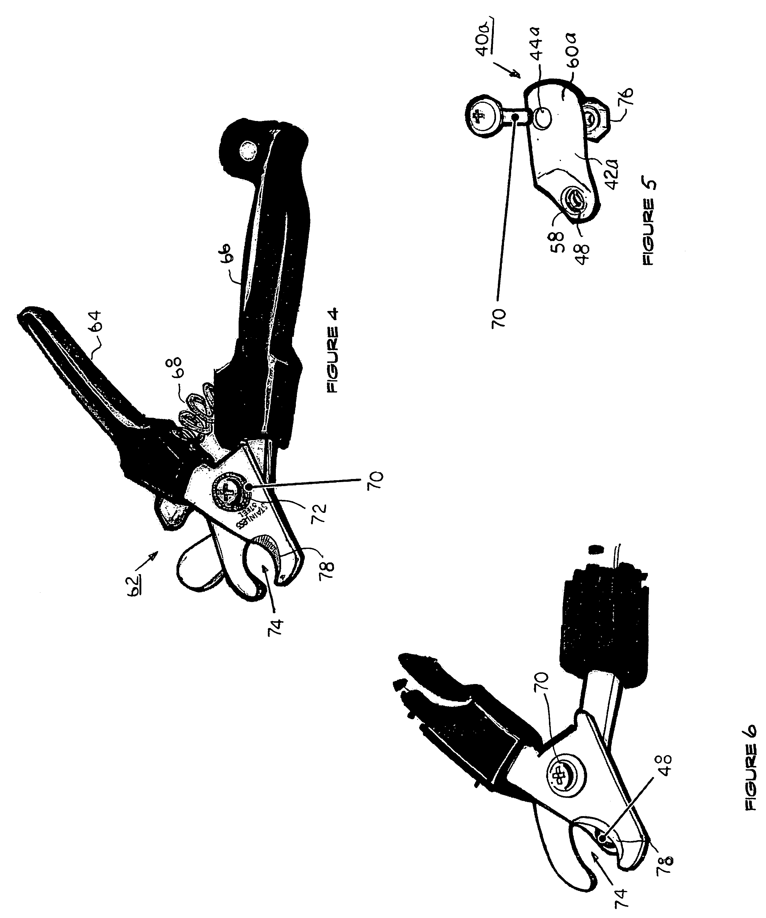
[0026]FIG. 5 shows an exploded perspective view of another lighting device 40a in accordance with the present invention. The structure of the semiconductor lighting device 40a has the electric power source and switch (not shown), and the light-emitting element 48 all integrally assembled within a slightly different casing 42a from the previously described casing 42. The difference in casing 42a is that it is more elongated and defines a single through-hole 44a along a top wall 60a for receiving the existing screw 70 and nut 76 used with the cutting pliers 63 shown in FIG. 4. It should be understood that all other electrical and optical features of semiconductor lighting device 40a are the same as previously described for semiconductor lighting device 40.

[0027]Turning to FIG. 6, the semiconductor lighting device 40a is removably attached to the cutting pliers 62 by utilizing the same hole (not shown) provided for screw 70 and nut 76 using the through-hole 44a defined by casing 42a. B...

third embodiment

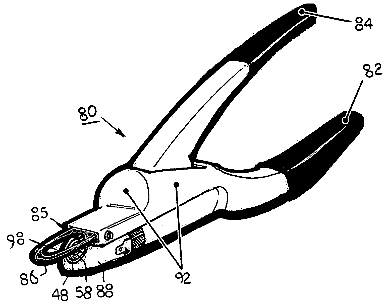
[0028]FIG. 7 is a perspective view of a nail clipper with lighting device in accordance with the present invention. As shown in FIG. 7 the nail clipper with lighting device 80 includes a stationary handle member 82, a pivoting handle member 84, and a cutting blade 86 connected to be actuated by the pivoting handle member 84. Once again, the cutting blade 84 is similar to that of a guillotine. The lower front portion 88 of stationary handle member 82 houses the switch 50 and light-emitting element 48. The upper front portion 88 of stationary handle member 82 provides a generally rectangular passage 85 in which cutting blade 86 may be slidably received in and out during a cutting operation.

[0029]Referring now to FIG. 9 there is shown a perspective view of the lower front portion 88 of nail clipper 80 wherein the electric power source 52, switch 50 and the light-emitting diode 48 are all integrally assembled within the lower front portion 88. The central portion 96 of stationary handle...


PUM


Abstract

A lighting device for use in combination with a nail clipper and cutting pliers is disclosed. The lighting device comprises a casing defining an angular front wall having an electric power source, a switch and a light-emitting element all integrally assembled and electrically connected within the casing. A radiation surface is mounted within the angular front wall for transmitting illumination light emitted from the light-emitting element wherein means for removably attaching the casing to either the nail clipper or cutting pliers are provided whereby the angle defined by the front wall positions the illumination light emitted from the light-emitting element for illuminating a blood vein or nerve through the animals nail such that the user does not strike or nick the blood vein or nerve during a cutting operation.

Description

BACKGROUND[0001]1. Field of the Invention[0002]The present invention relates to a lighting device attachment to a cutter useful as a nail clipper for trimming nails of an animal, such as a dog or cat. More particularly, it relates to a lighting device configured for use in combination with a nail clipper that provides a light source to illuminate the blood vein of the animal's nail providing a visual means for cutting the nail at a length that avoids nicking the blood vein which may result in bleeding and / or injury to the animal.[0003]2. Description of the Related Art[0004]Most animals dislike having their nails clipped. Many dogs object to nail cutting because someone has clipped their nails too short in the past and hurt them. Unlike human toenails, dogs' toenails have a nerve and a blood vein inside them. Often-times the animals squirm and move around making it difficult to clip off the desired amount. When cut too short, it causes pain and bleeding thus injuring the animal.[0005...

Claims


Application Information

Patent Timeline
Patent Type & Authority Patents(United States)
IPC IPC(8): B25B23/18
CPCA01K13/00A45D29/02Y10S362/80
Inventor VRSALOVIC, TATIANAGONZALES, ALEX
Owner VRSALOVIC TATIANA
Why Eureka
Try Eureka