Automatic identification of suspended particles

a technology of suspended particles and automatic identification, applied in the direction of fluorescence/phosphorescence, luminescent dosimeters, optical radiation measurement, etc., can solve the problems of inability to select fluorescent probes, inability to use selective fluorescent probes, and relatively slow methods

Active Publication Date: 2007-05-15
PROTEINSIMPLE
View PDF14 Cites 9 Cited by
  • Summary
  • Abstract
  • Description
  • Claims
  • Application Information

AI Technical Summary

Problems solved by technology

Unfortunately, these methods are still relatively slow, i.e. taking seconds per particle.
Automatic instruments, which can be used to identify and count sample particles, are of significant practical importance because microscopic analysis requires high skill level and is extremely time consuming, particularly when the concentration of the target species within the overall population is small.
This technique only works well if each of the target particles provides resolvably different signals for one or more of these measurements.
A number of limitations exist with fluorescence tagging methods in the analysis of natural samples, including: selective fluorescent probes are not available or possible for all species; the target entity may not provide a sufficiently distinct optical fluorescence and scattering signature for differentiating from other species; and there may be difficulties in preventing the fluorescent probe compound from attaching to one or more of the wide variety of species, other than the target species, contained within such samples.
While flow cytometry does utilize particle morphology information, as derived from scattering signals, the information contained in these signals is limited, especially for particles greater than approximately 5 microns.
Unfortunately, depth positioning of the particles must be within a few microns, because the allowed depth of focus is very small for high-magnification, high-quality images, typically 3.5 microns for a X10 objective.
Manual microscopic techniques enable both fluorescent and non-fluorescent images of individual particles to be used in particle identification; however, automatic techniques, which use both types of images, do not exist.
Up until now, considerable limitations in the processing rate and system design, which a simultaneous requirement for high quality image formation would normally impose, have prevented such a system from existing.
These requirements impose significant restrictions on instrument design, which will further reduce performance in the fluorescence and scattering mode relative to an instrument designed solely for this mode.

Method used


Image

  • Automatic identification of suspended particles
  • Automatic identification of suspended particles

Examples


Embodiment Construction

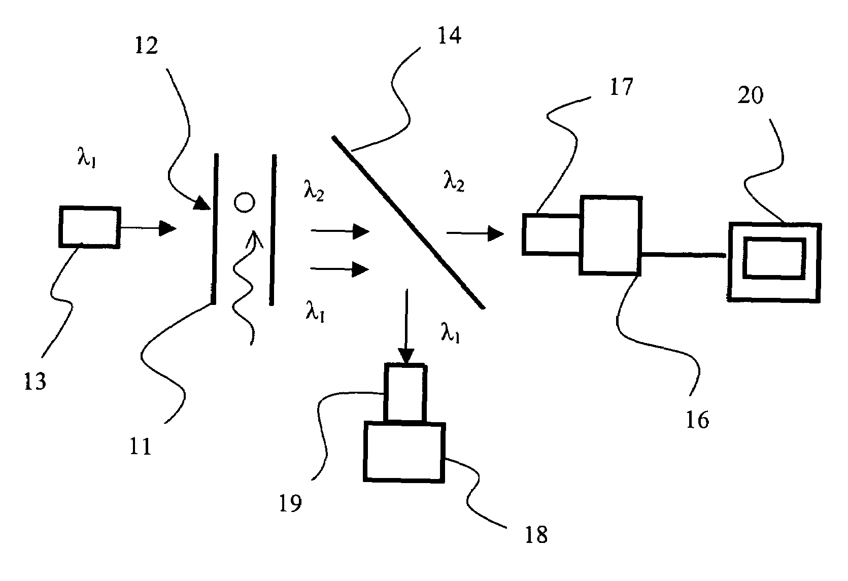
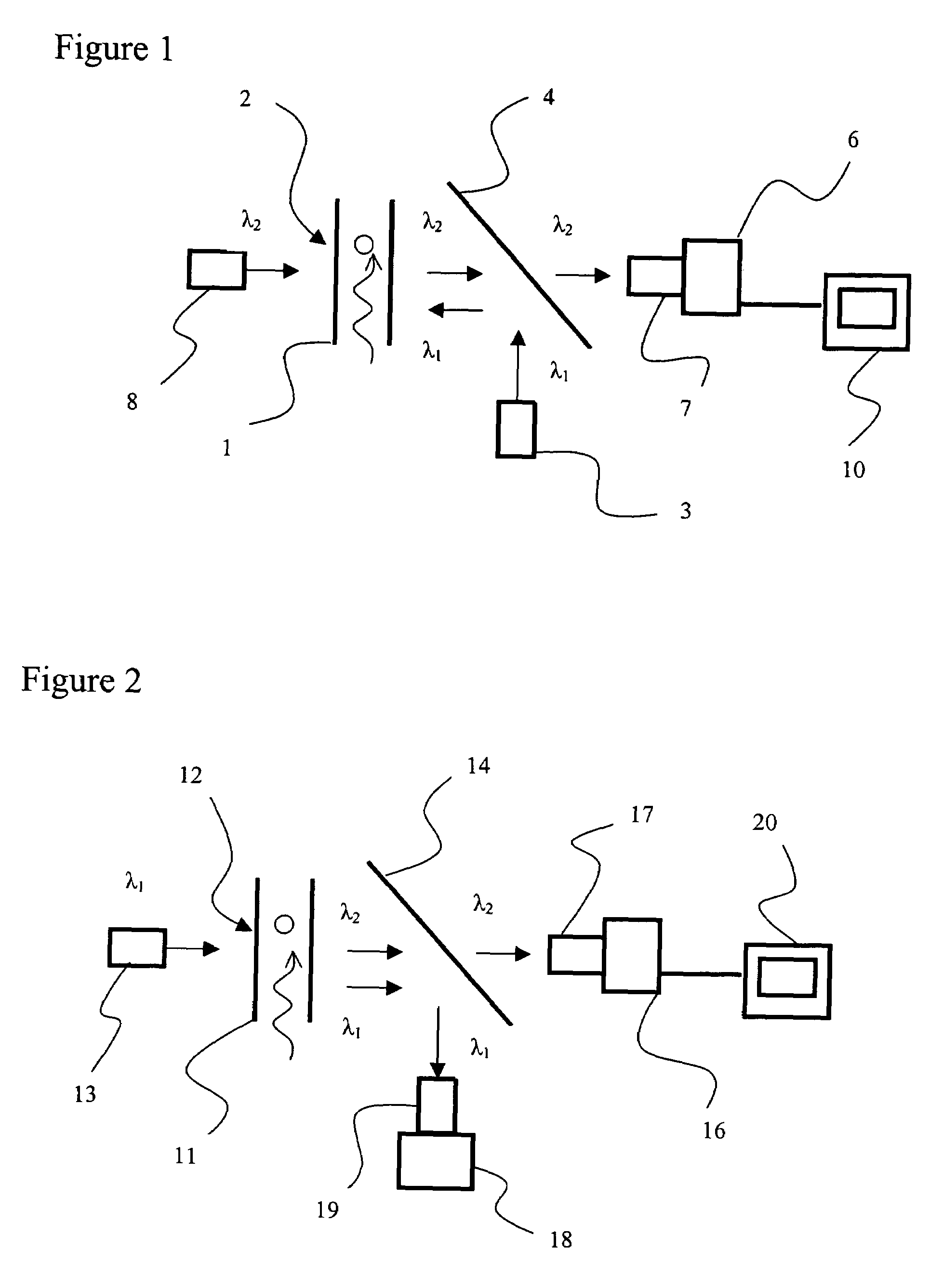
[0036]The present invention is based on the recognition that a digital optical imaging system can derive significant morphological information for a particle even when the system is operated under optical conditions such that the image contains levels of distortion, which would be unacceptable using conventional visual techniques. Specifically, the system can be operated: a) using a smaller number of pixels, e.g. 9 to 200, preferably 15 to 100, than that conventionally used for high quality imaging, thereby increasing processing speed; b) employing diffraction enlargement of particles, thereby allowing a reduction in the magnification and an increase in the depth of field, which relaxes the requirement for precise positioning of a particle or allowing multiple particles to be imaged simultaneously; c) employing particle velocities, which give rise to a finite degree of streaking; and d) employing a sample depth, which allows some particles to be partially out-of-focus.

[0037]A first ...


PUM

PropertyMeasurementUnit
depthaaaaaaaaaa
fluorescentaaaaaaaaaa
wavelengthaaaaaaaaaa

Abstract

The present invention relates to the automatic analysis and identification of different species of particles in a liquid sample using both fluorescent tagging and magnification techniques. A light source at a first wavelength is used to induce the tagged particles to emit light at a second wavelength, while the image thereof is captured on a pixel array of a digital camera. A second camera can be used to capture an image of the particles illuminated at the first wavelength, which is separated from the second wavelength by an optical filter. Alternatively, a second light source emitting pulses of light at the second wavelength, which alternate with the first light source.

Description

CROSS-REFERENCE TO RELATED APPLICATIONS[0001]The present invention claims priority from U.S. Patent Application No. 60 / 523,677 filed Nov. 21, 2004, which is incorporated herein by reference.TECHNICAL FIELD[0002]The present invention relates to a method and apparatus for automatically identifying and counting sub-populations of species within an overall population contained within a flowing stream of transparent liquid, and in particular to particle species identification through a combination of fluorescent tagging and detection and, automated image analysis.BACKGROUND OF THE INVENTION[0003]Suspended particle populations found in the water, environmental and medical applications are often composed of many different inorganic, organic and mixed sub-populations. Among these, certain biological species are of particular concern as indicators of pathogen presence or of contamination.[0004]Fluorescent tagging methods are commonly used to identify and count biological species. Fluorescent...

Claims


Application Information

Patent Timeline
Patent Type & Authority Patents(United States)
IPC IPC(8): G01J1/58G01N21/64G01N15/14G01N21/84
CPCG01N15/147G01N21/645G01N2021/6482G01N2021/6441G01N2015/1486
Inventor KING, FREDERICK DAVID
Owner PROTEINSIMPLE
Why Eureka
Try Eureka