System and method to control a rotary-linear actuator

a technology of linear actuator and actuator, which is applied in the field of motors, can solve the problems of adding significantly to the system described in the patent is limited to the movement in the plane, and the effect of reducing the manufacturing cost of the system

Inactive Publication Date: 2007-05-15
ANORAD
View PDF20 Cites 74 Cited by
  • Summary
  • Abstract
  • Description
  • Claims
  • Application Information

AI Technical Summary

Problems solved by technology

The traversing system described in the patent is, however, limited to movement in a plane.
While the harnesses provide an effective means of communication and power, they tend to add significantly to the manufacturing cost of the system.

Method used


Image

  • System and method to control a rotary-linear actuator
  • System and method to control a rotary-linear actuator
  • System and method to control a rotary-linear actuator

Examples


Embodiment Construction

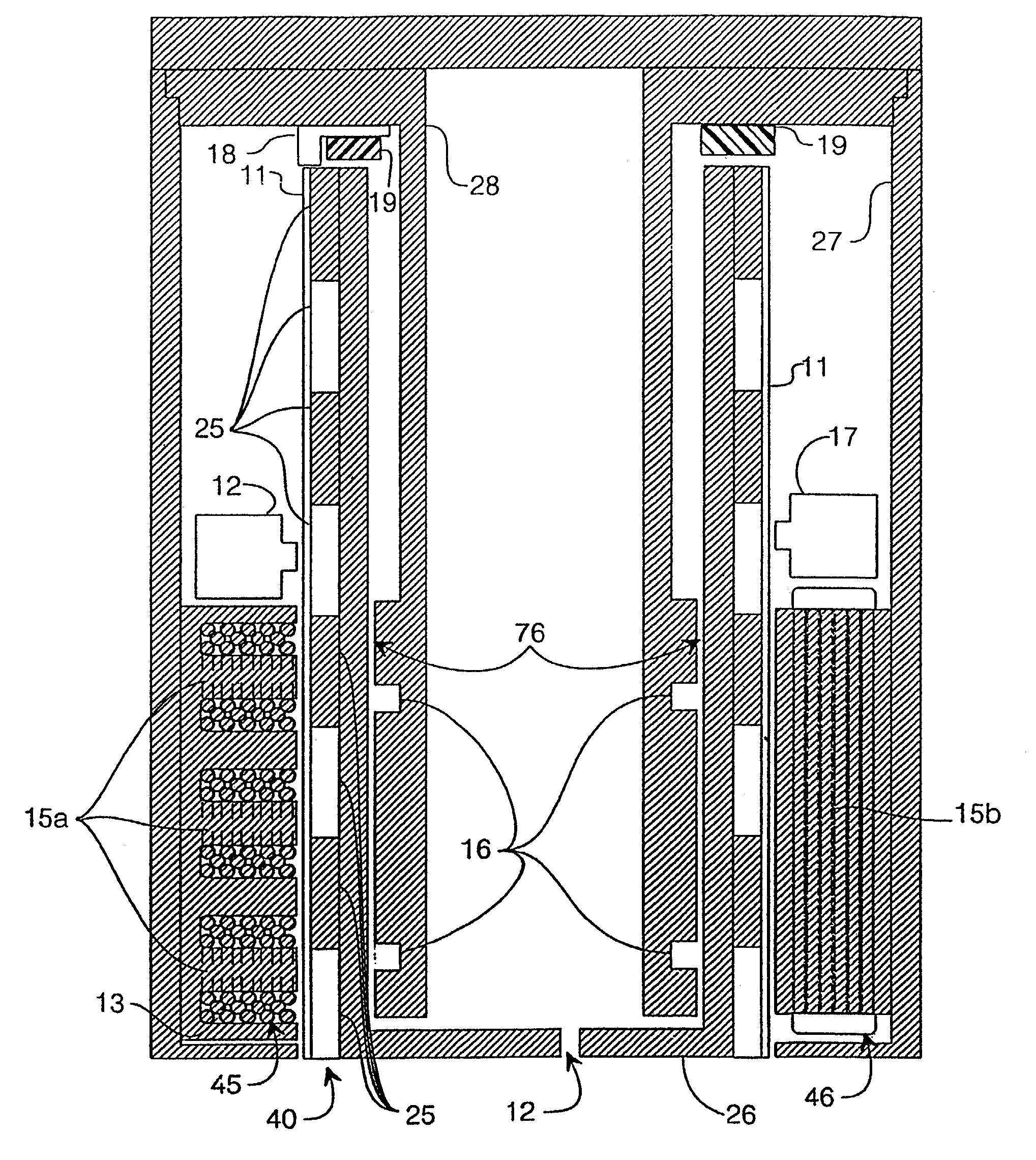
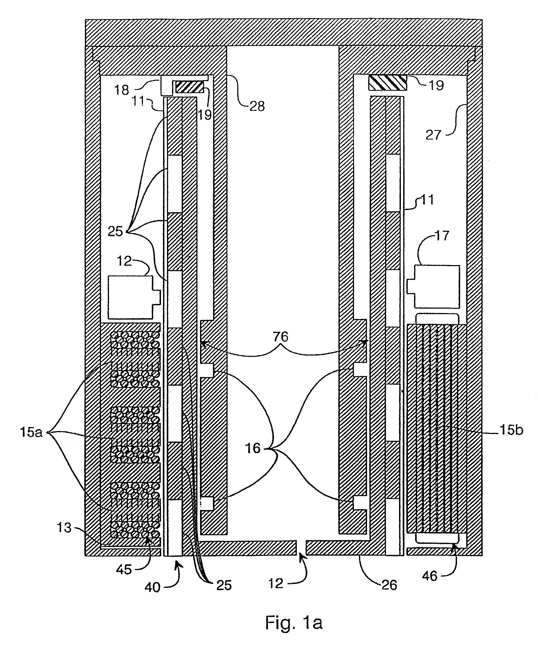
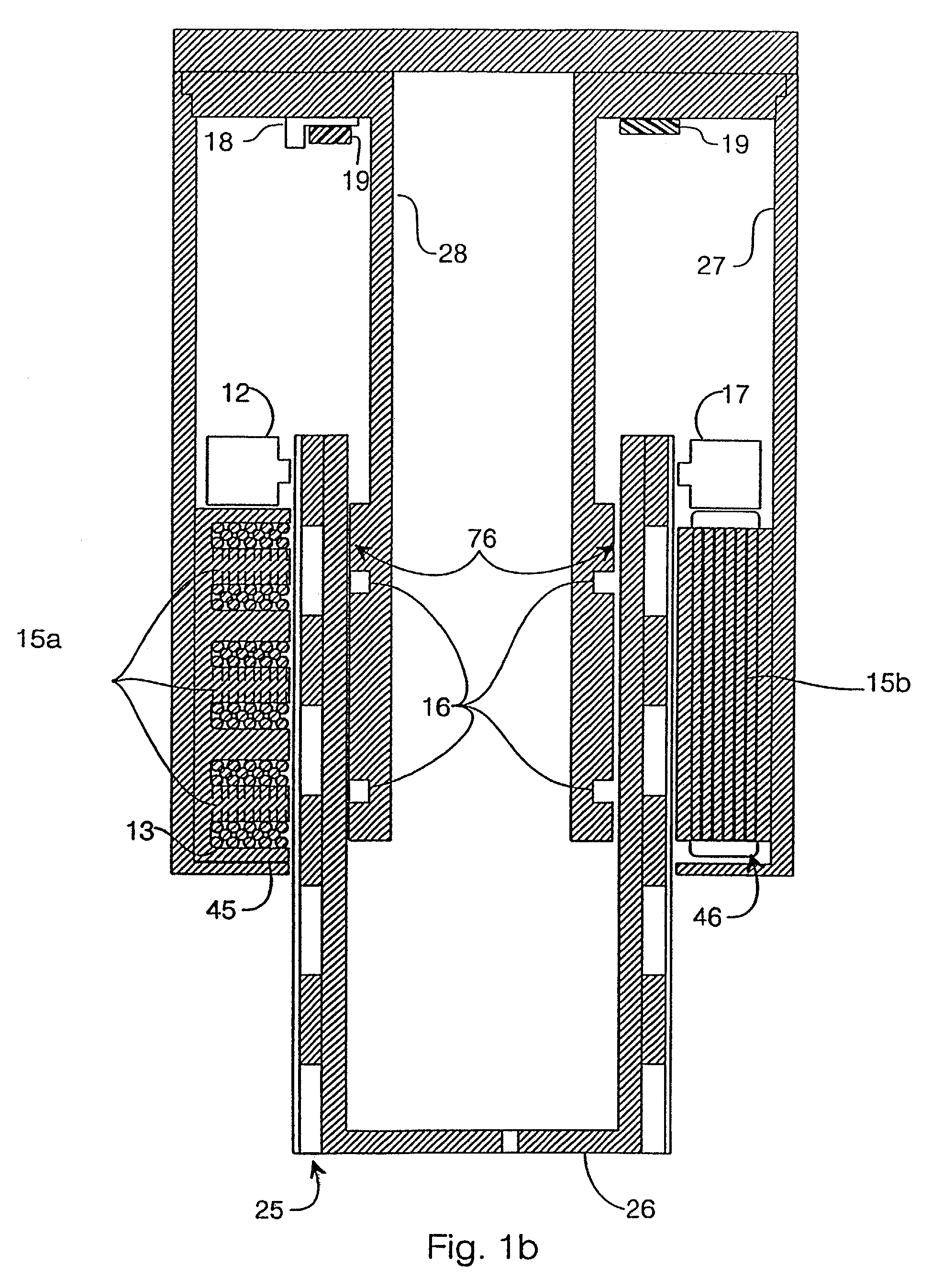
[0031]Referring to FIGS. 1a, 1b, 6a–6c, and 7a, in an embodiment of the invention, a cylindrical plunger element 26 floats on an air bearing 76 in a well formed by a motor support 27 and an air bearing support 28. A surface defining the well has a groove 16 through which air is distributed to form air bearing 76. Appropriate orifices and pockets (not shown) are supplied as required according to known techniques for making air bearings. Plunger element 26 is free to move axially and rotate about its axis supported on air bearing 76. Plunger element 26 has an array of magnets 25 covering an outside surface thereof. Half of magnets 25 are oriented so that their north poles point radially outward and an equal number are oriented so that their north poles point radially inward. Referring momentarily to FIG. 6a, a flat projection of the arrangement of magnets 25 shows their relationship to each other. Magnets 25 include outward-oriented magnets 25a and inward oriented magnets 25b arranged...


PUM


Abstract

A system and method are disclosed for controlling an integrated rotary-linear actuator system that may be coupled to a network via a network interface. The integrated rotary-linear actuator system includes a control system and a rotary-linear actuator having a moveable plunger and associated coils. The coils may be energized to interact with associated magnets to effect corresponding movement of the plunger, which may include rotation and / or linear movement. The network interface facilitates receipt of control information at the control system of the integrated rotary-linear actuator system from the network. The control system may control an amplifier to energize the coils based on the control information.

Description

RELATED APPLICATION[0001]The present application is a continuation-in-part of application Ser. No. 09 / 415,562, filed Oct. 8, 1999, now U.S. Pat. No. 6,215,206 and entitled ROTARY-LINEAR ACTUATOR, which is a continuation of application Ser. No. 08 / 668,705, which was filed Jun. 24, 1996 now U.S. Pat. No. 6,137,195, and entitled ROTARY-LINEAR ACTUATOR, now U.S. Pat. No. 6,137,195.TECHNICAL FIELD[0002]The present invention relates to motors and, more particularly, to a system and method to control a rotary-linear actuator.BACKGROUND OF THE INVENTION[0003]Various kinds of robotic actuators are known that provide multiple degrees of freedom. There is a need in the field for actuators that provide high accuracy, low weight, large load-carrying capacity, compact size, smooth operation, and cost-effectiveness. One known type of actuator that provides two-degrees of freedom, which scores highly in terms of the above design goals, is an entire class of so-called X-Y traversing systems, for exa...

Claims


Application Information

Patent Timeline
Patent Type & Authority Patents(United States)
IPC IPC(8): H02K41/00F16C39/06H02K33/12
CPCH02K21/14H02K41/03H02K2201/18H02K16/00
Inventor CHITAYAT, ANWARFAIZULLABHOY, MUSTANZIR
Owner ANORAD
Why Eureka
Try Eureka