Induction motor with integrated sensor

a technology of induction motor and sensor, which is applied in the direction of electrical apparatus, control systems, dynamo-electric machines, etc., can solve the problems of inconvenient installation, and high cost of external sensors, and achieves low cost and inexpensive and reliable effects

Inactive Publication Date: 2007-05-15
DANAHER MOTION STOCKHOLM AB
View PDF5 Cites 17 Cited by
  • Summary
  • Abstract
  • Description
  • Claims
  • Application Information

AI Technical Summary

Benefits of technology

[0007]An object of the present invention is to provide an induction motor with an inexpensive and reliable integrated sensor for sensing the position and / or speed of the motor.
[0012]Thus there is provided an induction motor with integrated sensor which is both inexpensive and reliable. Because no or only small modifications of a conventional stator are required, standard low cost stators can be used. There is only a minor modification from a standard rotor, if any. The central Y-tap of Y-connected stator windings is easily made available, making the required sensing of winding inductances feasible.

Problems solved by technology

However, the use of an external sensor is accompanied with drawbacks.
Firstly, an external sensor is expensive because of the very accurate mechanical and electronic components included therein.
Secondly, because an external sensor by its very nature is mounted externally, it is prone to damage and also requires installation.
However, the described solution requires specially punched laminations increasing manufacturing costs, and standard manufacturing methods are not applicable for all cases.
The disclosed solution will not work at near zero speed and will not detect the direction of rotation.
Further, the design of the motor is not disclosed.

Method used


Image

  • Induction motor with integrated sensor
  • Induction motor with integrated sensor
  • Induction motor with integrated sensor

Examples


Embodiment Construction

[0024]In the following a detailed description of preferred embodiments of the present invention will be given.

[0025]Note that unless otherwise stated the following description will describe the motor properties at a frequency that is suitable for the sensor signal, such as 1–10 kHz, and not the normal operating frequency of the motor, such as between 0 and 500 Hz.

[0026]In this description, in some instances reference is made to stator and rotor laminations and slots therein while in other instances reference is made to stators and rotors and slots therein. It will be appreciated that the inventive idea is applicable to entire induction motors comprising stator and rotor made up of stacks of laminations and that the varying references are for ease of understanding only.

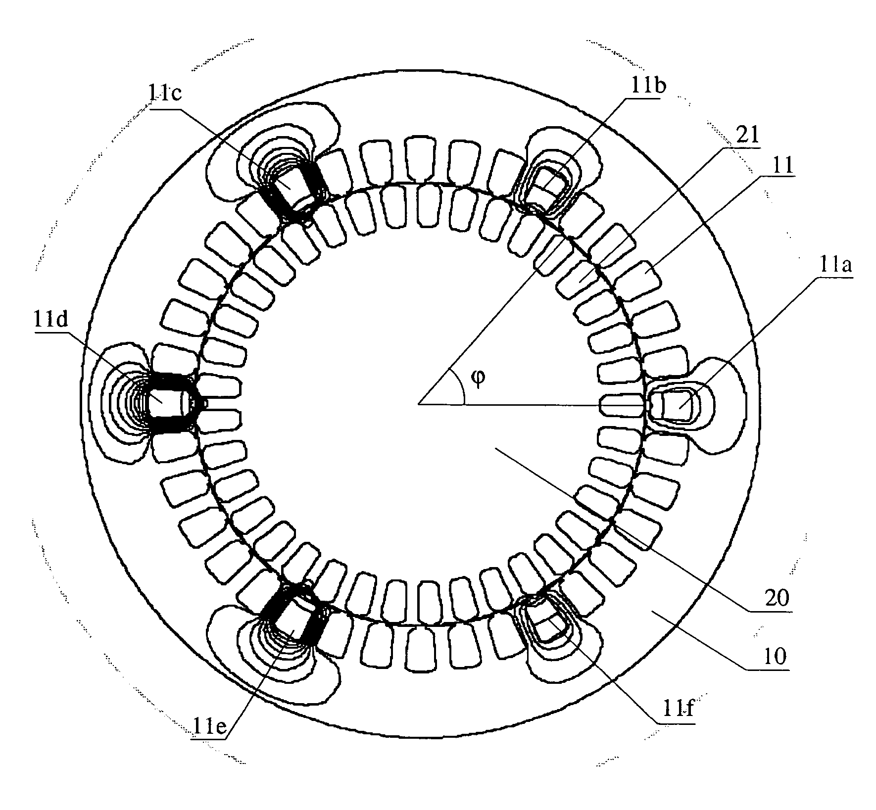
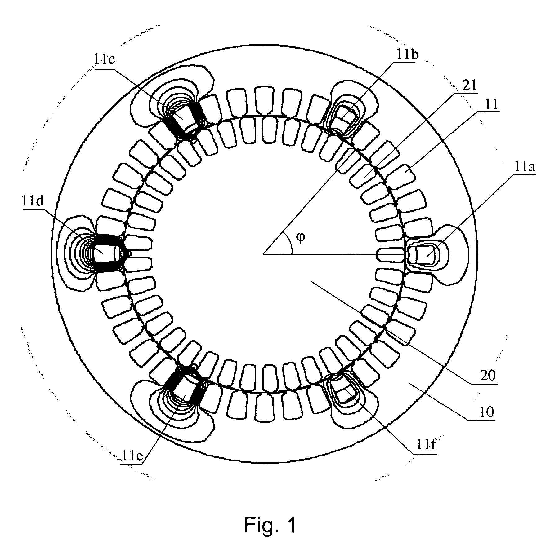
[0027]FIG. 1 shows a finite element simulation of the magnetic flux created in induction motor stator and rotor laminations. A stator lamination 10 is provided with 36 identical slots 11 evenly distributed around the i...


PUM


Abstract

An induction motor comprises a stator (10) and a rotor (20), which includes material essentially blocking magnetic flux at high frequencies. A difference in number of stator slots and rotor slots is chosen so that the inductance of a winding provided in a stator slot is different from the inductance of a winding provided in another stator slot. A sense means, such as stator winding or separate sense winding, is provided in at least one of the stator slots and the sense means is arranged to allow measuring of the inductance thereof. The sense means constitutes an integrated sensor, which is both inexpensive and reliable. A method of sensing the rotor position and / or speed of an induction motor is also described.

Description

[0001]The present application claims priority under 35 U.S.C. § 119 to Swedish patent application number 0401838-8, filed Jul. 9, 2004.FIELD OF INVENTION[0002]The present invention generally relates to an electrically controlled induction motor where a speed and / or position feedback signal is needed to accurately control the speed and / or position and more specifically to an induction motor with integrated sensor. The invention also relates to a method of sensing the speed and / or position of a rotor in an induction motor.BACKGROUND[0003]A speed / position sensor is often needed for controlling an induction motor by a controller (drive), especially at close to zero speed. This is conventionally accomplished by attaching an external sensor to the motor shaft. However, the use of an external sensor is accompanied with drawbacks. Firstly, an external sensor is expensive because of the very accurate mechanical and electronic components included therein. Secondly, because an external sensor ...

Claims


Application Information

Patent Timeline
Patent Type & Authority Patents(United States)
IPC IPC(8): H02K11/00H02KH02K17/30
CPCH02K17/30H02K17/16H02K3/28H02K1/165H02K1/265H02P7/00H02P23/00
Inventor NILSON, THORD AGNE GUSTAF
Owner DANAHER MOTION STOCKHOLM AB
Why Eureka
Try Eureka