Method and device for boresighting an antenna on a moving platform using a moving target

a technology of moving target and antenna, which is applied in the field of boresighting antennas on moving platforms, can solve the problems of increased cost, boresight errors, and undesirable closed loop pointing

Active Publication Date: 2007-05-15
L3 TECH INC
View PDF45 Cites 54 Cited by
  • Summary
  • Abstract
  • Description
  • Claims
  • Application Information

AI Technical Summary

Benefits of technology

[0007]It has been recognized that it would be advantageous to develop a technique for boresighting an ante...

Problems solved by technology

Closed loop pointing systems typically require complex feed arrangements or complex receiver signal processing, which can increase cost.
Hence, in many applications, closed loop pointing is undesirable.
Various sources of error can occur in an antenna system which results in boresight errors.
There can, however, be alignment errors between the axes of the antenna system and the axes of the attitude reference system.
These alignment errors result in misalignment or boresight error between the desired and actual antenna pointing direction.
Other potential sources of boresight error include mechani...

Method used


Image

  • Method and device for boresighting an antenna on a moving platform using a moving target
  • Method and device for boresighting an antenna on a moving platform using a moving target
  • Method and device for boresighting an antenna on a moving platform using a moving target

Examples


Embodiment Construction

[0020]Reference will now be made to the exemplary embodiments illustrated in the drawings, and specific language will be used herein to describe the same. It will nevertheless be understood that no limitation of the scope of the invention is thereby intended. Alterations and further modifications of the inventive features illustrated herein, and additional applications of the principles of the invention as illustrated herein, which would occur to one skilled in the relevant art and having possession of this disclosure, are to be considered within the scope of the invention.

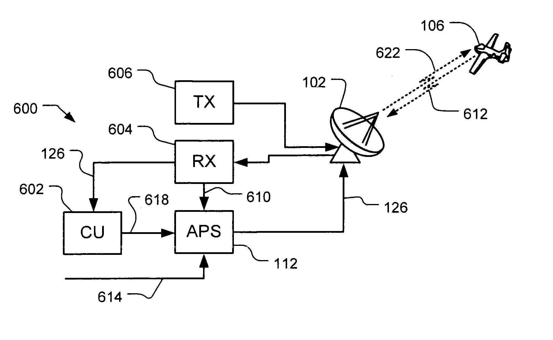
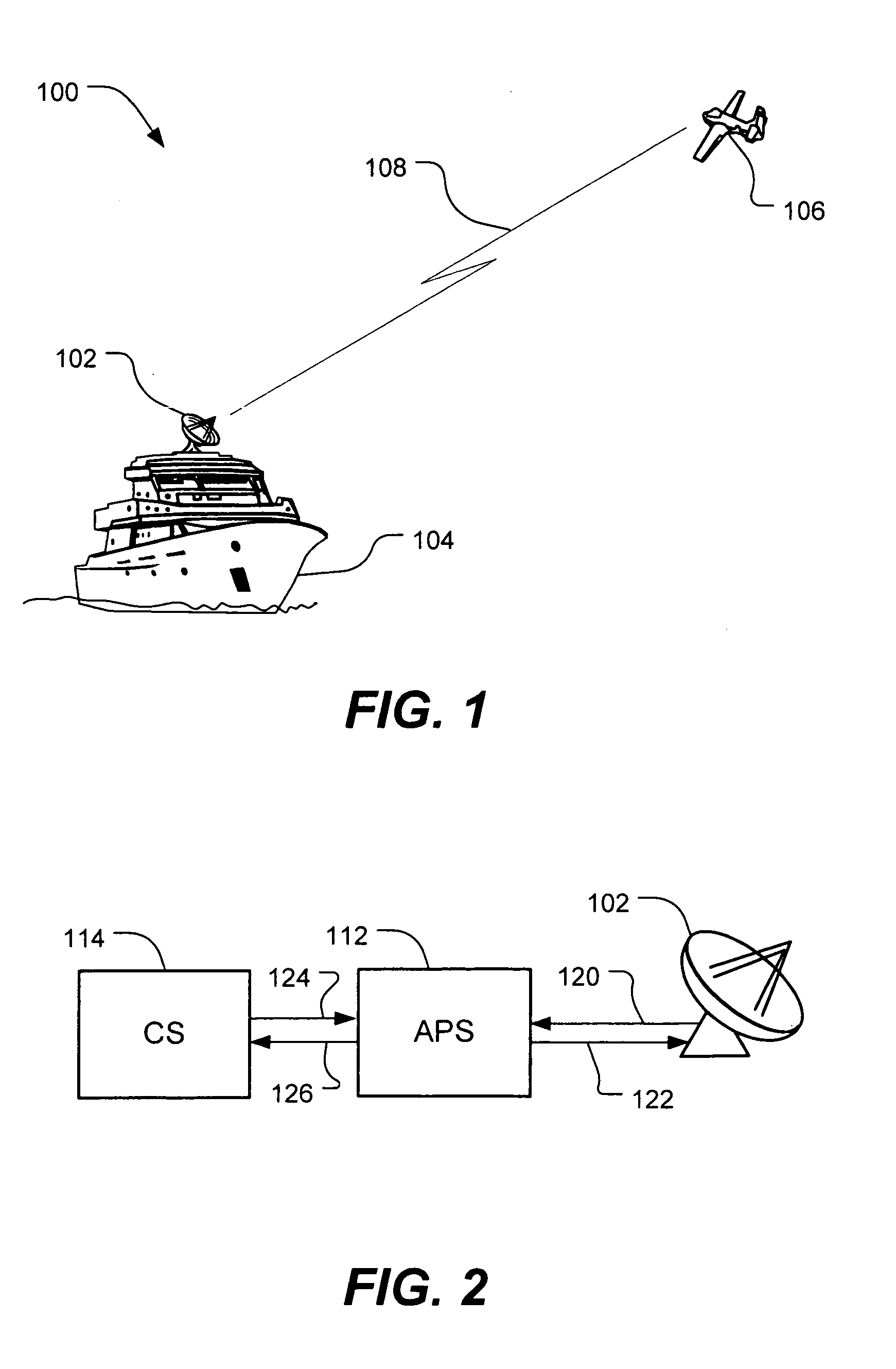
[0021]FIG. 1 illustrates a system for boresight calibrating an antenna mounted on a moving platform using a concurrently moving calibration target in accordance with an embodiment of the present invention. The antenna 102 is mounted on a moving platform 104, for example a ship at sea. The calibration target 106, for example a satellite, aircraft, or unmanned airborne vehicle, is concurrently moving. Target navigat...


PUM


Abstract

A technique for boresighting an antenna mounted on a moving platform is described. The technique uses a concurrently moving calibration target. Target navigation data and platform navigation data are used to compensate for movement of the target and the platform. The antenna pointing direction is biased in a direction which provides a best signal quality, and the bias used to determine antenna boresight calibration factors. The boresight correction factors can be used for open loop pointing.

Description

FIELD OF THE INVENTION[0001]The present invention relates generally to antenna boresighting, and more particularly to boresighting an antenna on a moving platform using a moving calibration target.BACKGROUND[0002]Communications systems often use directional antennas to focus transmitted and received power in a desired direction. The direction of maximum transmitted and received power is sometimes referred to as the “boresight” of the antenna. Highly directional or narrow beamwidth antennas must be pointed accurately to ensure the antenna boresight is oriented in the desired direction. For example, for communication between two moving platforms, narrow beamwidth antennas are constantly adjusted as the pointing angles change due to relative movement of the platforms. Additional stabilization may also be required to accommodate changes in platform orientation, for example, using an inertial reference that relates the platform orientation (roll, pitch, and yaw / heading) to the earth.[000...

Claims


Application Information

Patent Timeline
IPC IPC(8): G01S7/40G01S13/00
CPCG01S7/4026G01S2007/403G01S2007/4034G01S2007/4091G01S7/403G01S7/4034G01S7/4091
Inventor WEBSTER, JR., JAMES B.TIMOTHY, LAMAR KSTROHACKER, FRED M.
Owner L3 TECH INC
Why Eureka
Try Eureka