Developing device, process cartridge, developer layer regulating member, and developer layer regulating member attaching method

a technology of developer layer and developer layer, which is applied in the direction of electrographic process apparatus, instruments, optics, etc., can solve the problems of limiting the miniaturization of the member acting on the components, and the limitation of the miniaturization of the developing roller, etc., to achieve the effect of improving the miniaturization

Inactive Publication Date: 2007-05-15
CANON KK
View PDF21 Cites 58 Cited by
  • Summary
  • Abstract
  • Description
  • Claims
  • Application Information

AI Technical Summary

Benefits of technology

[0011]It is an object of the present invention to provide a developer layer regulating member capable of achieving improved miniaturization, and a developing device and a process cartridge which are provided with the developer layer regulating member.
[0012]It is another object of the present invention to provide a developer layer regulating member capable of achieving enhanced ease of assembly, and a developing device and a process cartridge which are provided with the developer layer regulating member.
[0013]It is another object of the present invention to provide a developer layer regulating member capable of achieving improved miniaturization and enhanced ease of assembly, and a developing device and a process cartridge which are provided with the developer layer regulating member.
[0014]It is another object of the present invention to provide a developer layer regulating member attaching method capable of achieving enhanced ease of assembly.

Problems solved by technology

However, the sizes of components such as a developing roller that carries developer in a developing device, an electrophotographic photosensitive drum that is an image bearing member on which an electrostatic image is formed, etc., depend on the size of desired image formation, which inevitably puts a limit on the miniaturization of those components.
This also puts a limit on the miniaturization of members acting on those components, for example, a developer layer regulating member that regulates the thickness of a developer layer on the circumferential surface of a developer roller.
Therefore, there is a limit to the miniaturization of the developing roller.
Therefore, there is a limit to achieving miniaturization of the developer layer regulating member through a reduction in the distance between the fitting portion and the screw hole by bringing them closer to each other.

Method used


Image

  • Developing device, process cartridge, developer layer regulating member, and developer layer regulating member attaching method
  • Developing device, process cartridge, developer layer regulating member, and developer layer regulating member attaching method
  • Developing device, process cartridge, developer layer regulating member, and developer layer regulating member attaching method

Examples


embodiment 1

(1) [General Overall Construction of Image Forming Apparatus]

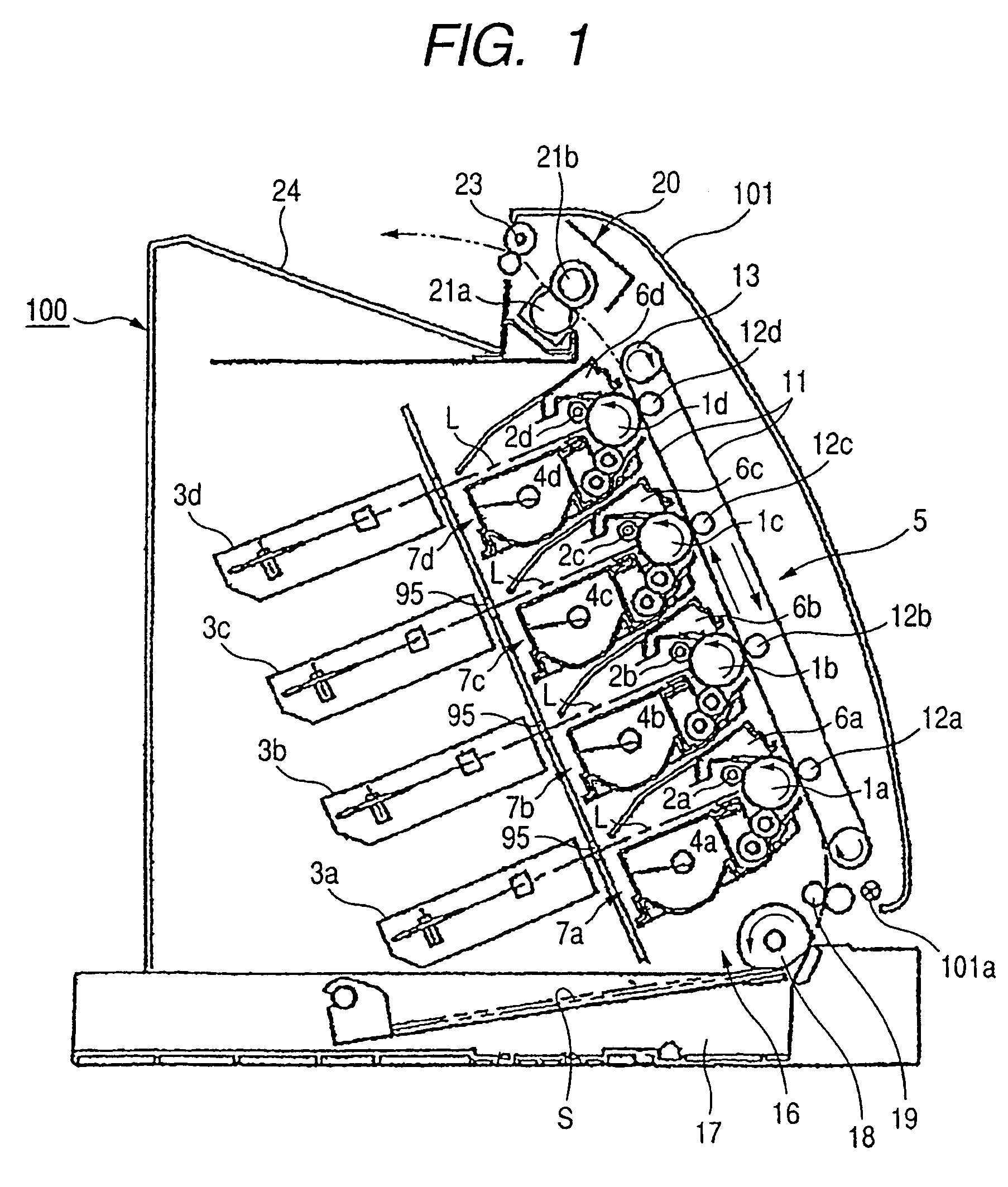
[0033]FIG. 1 is a schematic cross-sectional view showing the general overall construction of a multi-color image forming apparatus according to Embodiment 1 of the present invention. The multi-color image forming apparatus is a full-color laser beam printer of a vertical-tandem type or a detachable process-cartridge type employing a transfer-type electrophotographic process.

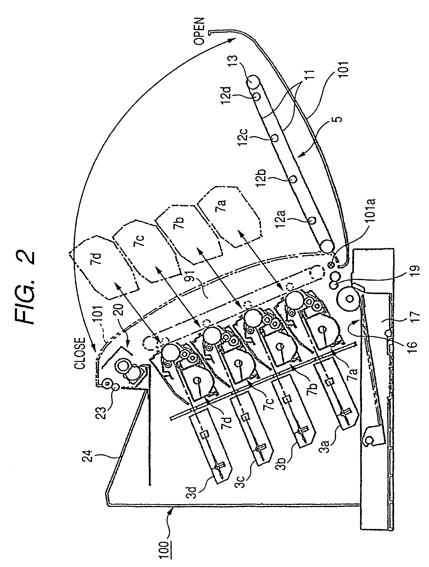
[0034]An image forming apparatus main body 100 (hereinafter referred to as the “apparatus main body”) has an apparatus front cover (hereinafter referred to as the “front cover”) 101. The front cover 101 is openable and closable relative to the front side portion of the apparatus main body 100 about a hinge shaft 101a on the bottom edge side thereof. FIG. 1 shows a state where the front cover 101 is closed with respect to the apparatus main body 100. FIG. 2 shows a state in which the front cover 101 is opened frontward to expose a process cartridge inser...

embodiment 2

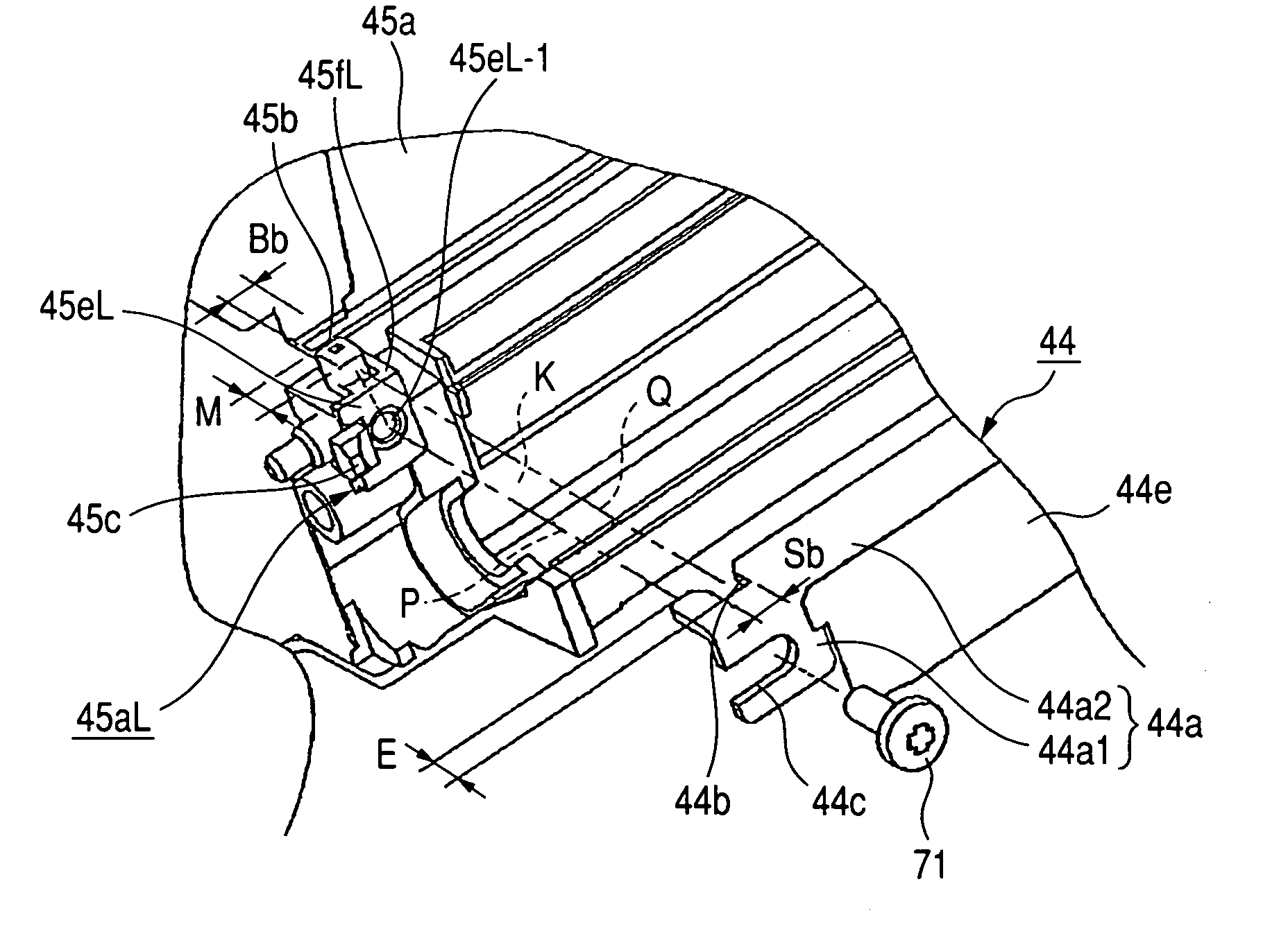
[0096]In Embodiment 1, the description is directed to the developing blade 44 and the process cartridge equipped with the developing blade. However, the developing blade 44 may be provided to the developing device. In this case, the developing device is basically of the same construction as the developing unit 4A of the process cartridge described in Embodiment 1. As shown in FIG. 3, the developing device includes: the developing frames 45a and 45b that support the developing sleeve (developing roller) 40 rotating clockwise as indicated by the arrow, with a minute gap being maintained between the developing sleeve 40 and the photosensitive drum 1 by the spacer roller 40a; the toner supplying roller 43 that rotates clockwise as indicated by the arrow while in contact with the developing sleeve 40; and the developing blade 44. The developing frames 45a and 45b are jointed together by ultrasonic welding or the like, forming the developing container unit (developing container) 46. Furth...

embodiment 3

[0097]In Embodiments 1 and 2, the description is directed to the case of the groove portions 44c and 44d of a substantially U-shaped configuration which is cut open in the longitudinal direction of the developing blade 44. However, the groove portions 44c and 44d may not be cut open. That is, as shown in FIGS. 14A, 14B, and 13D, hole portions 344c and 344d are provided instead of the groove portions 44c and 44d. In this case, the construction other than the groove portions 44c and 44d is the same as that of Embodiment 1. Such an arrangement, too, makes it possible to achieve miniaturization of the developing blade. It is to be noted that in the construction of this embodiment, the longitudinal size of a developing blade 344 is slightly larger than the longitudinal size of the developing blade 44 of Embodiment 1.


PUM


Abstract

A developing device for developing a latent image formed on an image bearing member by using developer, the developing device including: a developing frame; a developing roller for supplying developer to the latent image to develop the latent image; a developer layer regulating member which regulates a layer thickness of developer on a circumferential surface of the developing roller; and a first surface and a second surface which are provided in the developer layer regulating member along a longitudinal direction of the developer layer regulating member, for positioning the developer layer regulating member with respect to the developing frame, in which a first imaginary plane, which is obtained by extending the first surface imaginarily, and a second imaginary plane, which is obtained by extending the second surface imaginarily, intersect each other.

Description

BACKGROUND OF THE INVENTION[0001]1. Field of the Invention[0002]The present invention relates to a developing device, a process cartridge, a developer layer regulating member, and a developer layer regulating member attaching method.[0003]2. Related Background Art[0004]In electrophotographic image forming apparatuses such as a copying machine, a laser printer, and a facsimile machine, an electrostatic latent image is formed through selective exposure on an electrophotographic photosensitive drum that is uniformly charged by a charging device. Developer is deposited onto the thus formed electrostatic latent image by a developing device, thus developing the electrostatic latent image as a developer image. The developer image is then transferred to a recording medium, thus forming an image on the recording medium. Then, a cleaning device removes from the electrophotographic photosensitive drum any developer remaining on the surface after the transfer of the developer image, thus leavin...

Claims


Application Information

Patent Timeline
Patent Type & Authority Patents(United States)
IPC IPC(8): G03G15/08
CPCG03G15/0812G03G2215/0634
Inventor TOBA, SHINJIROSATO, MASAAKI
Owner CANON KK
Why Eureka
Try Eureka