Magnetically enhanced injection catheter

a technology of injection catheter and injection tube, which is applied in the field of magic enhancement injection catheter, can solve the problems of limiting the efficiency of this delivery technique, the distal end of the needle not being effectively delivered to the target tissue, and the physician being unable to manipulate the distal portion of the injection catheter directly, so as to reduce the loss of therautic through ejection

Inactive Publication Date: 2007-05-15
BOSTON SCI SCIMED INC
View PDF32 Cites 72 Cited by
  • Summary
  • Abstract
  • Description
  • Claims
  • Application Information

AI Technical Summary

Benefits of technology

[0014]In another embodiment, the fluid comprises a therapeutic conjugated with ferromagnetic particles. In this embodiment, the magnetic field supplies a pulse which acts

Problems solved by technology

As with other types of catheters, the physician typically is not able to manipulate the distal portion of an injection catheter directly.
If the needle of the injection catheter inadvertently passes through the wall, the therapeutic or diagnostic agents dispensed from the distal end of the needle will not be effectively delivered to the target tissue.
One factor limiting the efficiency of this delivery

Method used


Image

  • Magnetically enhanced injection catheter
  • Magnetically enhanced injection catheter
  • Magnetically enhanced injection catheter

Examples


Embodiment Construction

[0022]The following detailed description should be read with reference to the drawings, in which like elements in different drawings are numbered in like fashion. The drawings, which are not necessarily to scale, depict selected embodiments and are not intended to limit the scope of the invention. In some cases, the drawings may be highly diagrammatic in nature. Examples of constructions, materials, dimensions, and manufacturing processes are provided for various elements. Those skilled in the art will recognize that many of the examples provided have suitable alternatives which may be utilized.

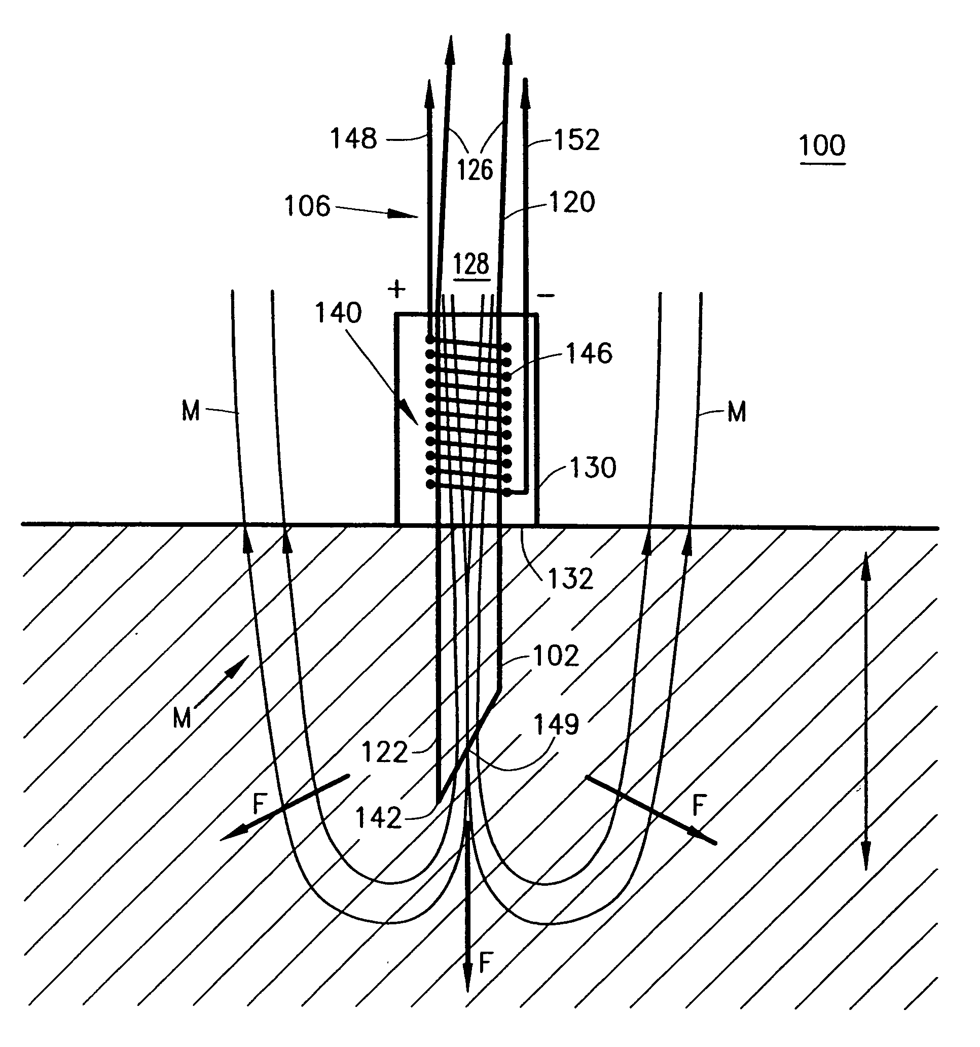
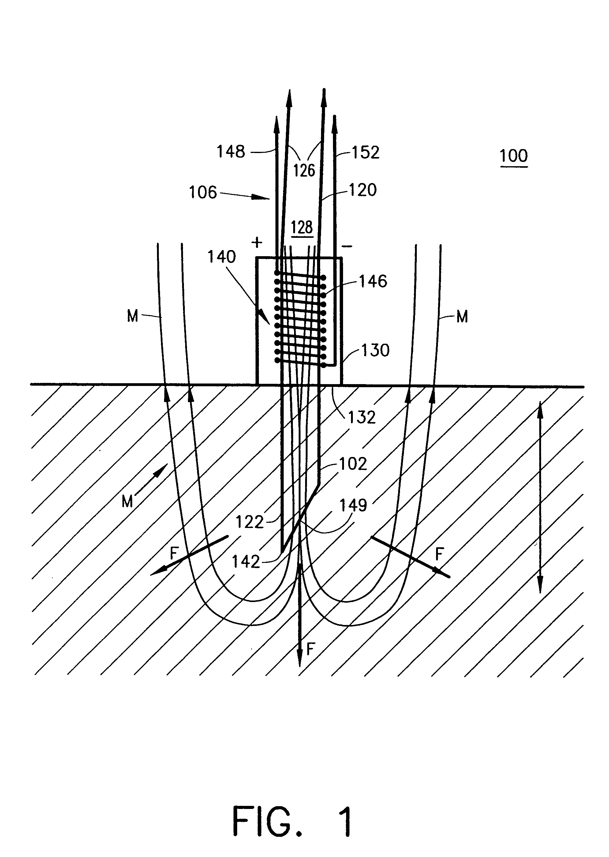
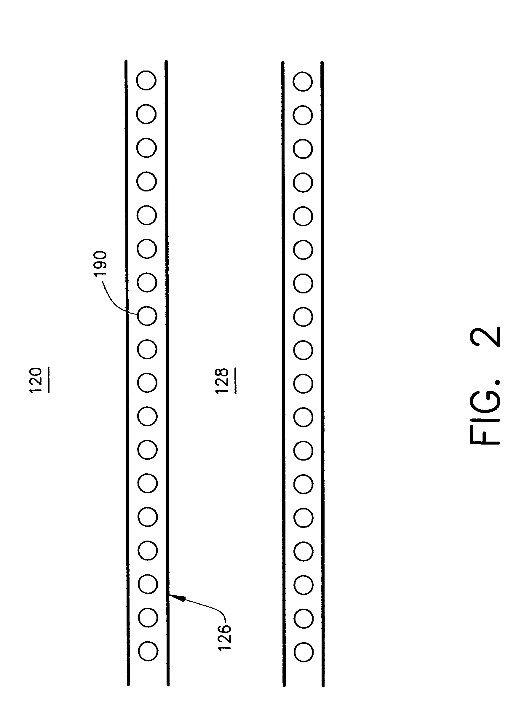
[0023]FIG. 1 is a plan view of a catheter 100 in accordance with the present invention. Catheter 100 has a distal end 102, a proximal end (not shown), and a shaft assembly 106. Shaft assembly 106 comprises a first elongated shaft 120 having a distal end 122, a proximal end (not shown), and an inside surface 126 defining a lumen 128. Shaft assembly 106 also includes a hood 130 disposed around ...


PUM


Abstract

A catheter adapted to deliver therapeutic or diagnostic agents to a target tissue of a human body is disclosed. A catheter in accordance with the present invention comprises a magnetic field source for directing the flow of the therapeutic of diagnostic agent. The therapeutic or diagnostic agent may be conjugated with diamagnetic particles, ferromagnetic particles, super paramagnetic particles, or paramagnetic particles.

Description

FIELD OF THE INVENTION[0001]The present invention relates generally to devices and methods for delivering therapeutic or diagnostic agents to a portion of the human body.BACKGROUND OF THE INVENTION[0002]Injection catheters are currently utilized in a wide variety of minimally invasive or percutaneous medical procedures. Generally, a catheter enables a physician to remotely perform a medical procedure by inserting the catheter into the vascular system of the patient at an easily accessible location and navigating the tip of the catheter to a desirable target site. By this method, virtually any target site in the patient's vascular system may be remotely accessed.[0003]Typically, a percutaneous procedure begins with the step of inserting a distal portion of the catheter into the patient's vasculature at a convenient location. Once the distal portion of the catheter has entered the patient's vascular system the physician may urge the distal tip forward by applying longitudinal forces t...

Claims


Application Information

Patent Timeline
IPC IPC(8): A61N1/30A61M31/00A61M37/00A61N1/00A61N2/00
CPCA61M37/00A61N2/002
Inventor FREYMAN, TOBY
Owner BOSTON SCI SCIMED INC
Why Eureka
Try Eureka