Arrangement in explosion joining of ends of wires and the like

a technology of end of wire and connection, applied in the direction of cable junction, connection contact member material, connection effected by explosion, etc., can solve the problems of inconvenient or impossible carrying such tools to the site, and achieve the effect of fast and easy

Active Publication Date: 2007-05-22
HUBBELL INC
View PDF7 Cites 8 Cited by
  • Summary
  • Abstract
  • Description
  • Claims
  • Application Information

AI Technical Summary

Benefits of technology

[0008]It is an object of the present invention to provide a method of joining ends of wires and the like which is cheaper, faster and easier to effect than prior art methods and apparatus.

Problems solved by technology

In view of the weight and bulk of the tools it may be inconvenient or impossible to carry such tools to the sites at which the joining is to be made.

Method used


Image

  • Arrangement in explosion joining of ends of wires and the like
  • Arrangement in explosion joining of ends of wires and the like
  • Arrangement in explosion joining of ends of wires and the like

Examples


Embodiment Construction

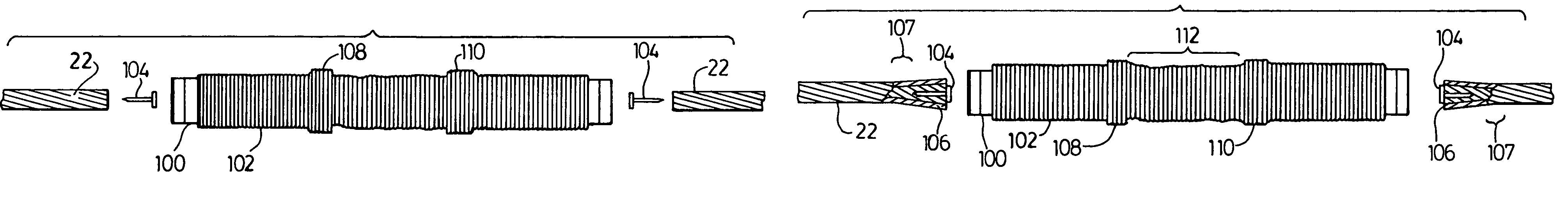
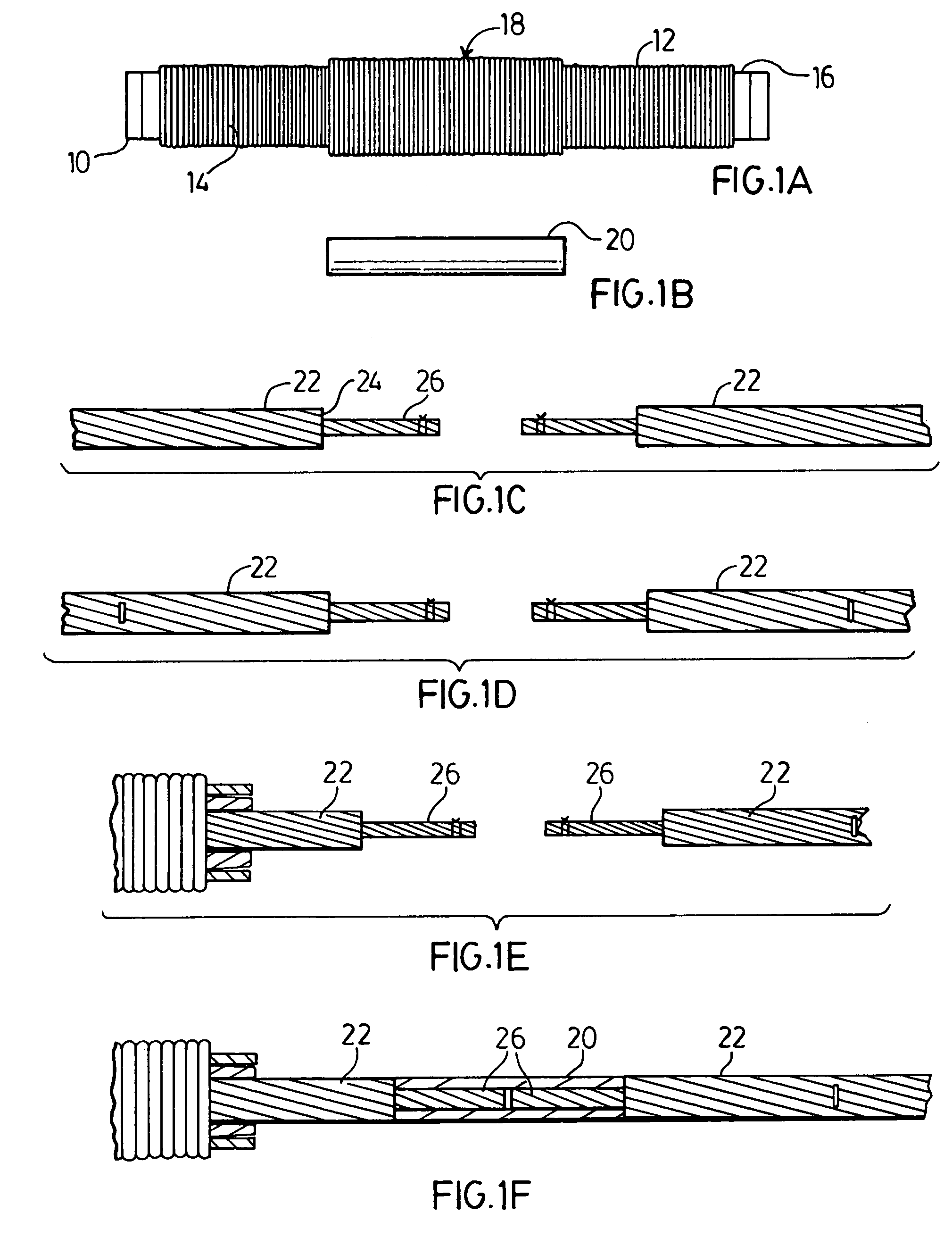
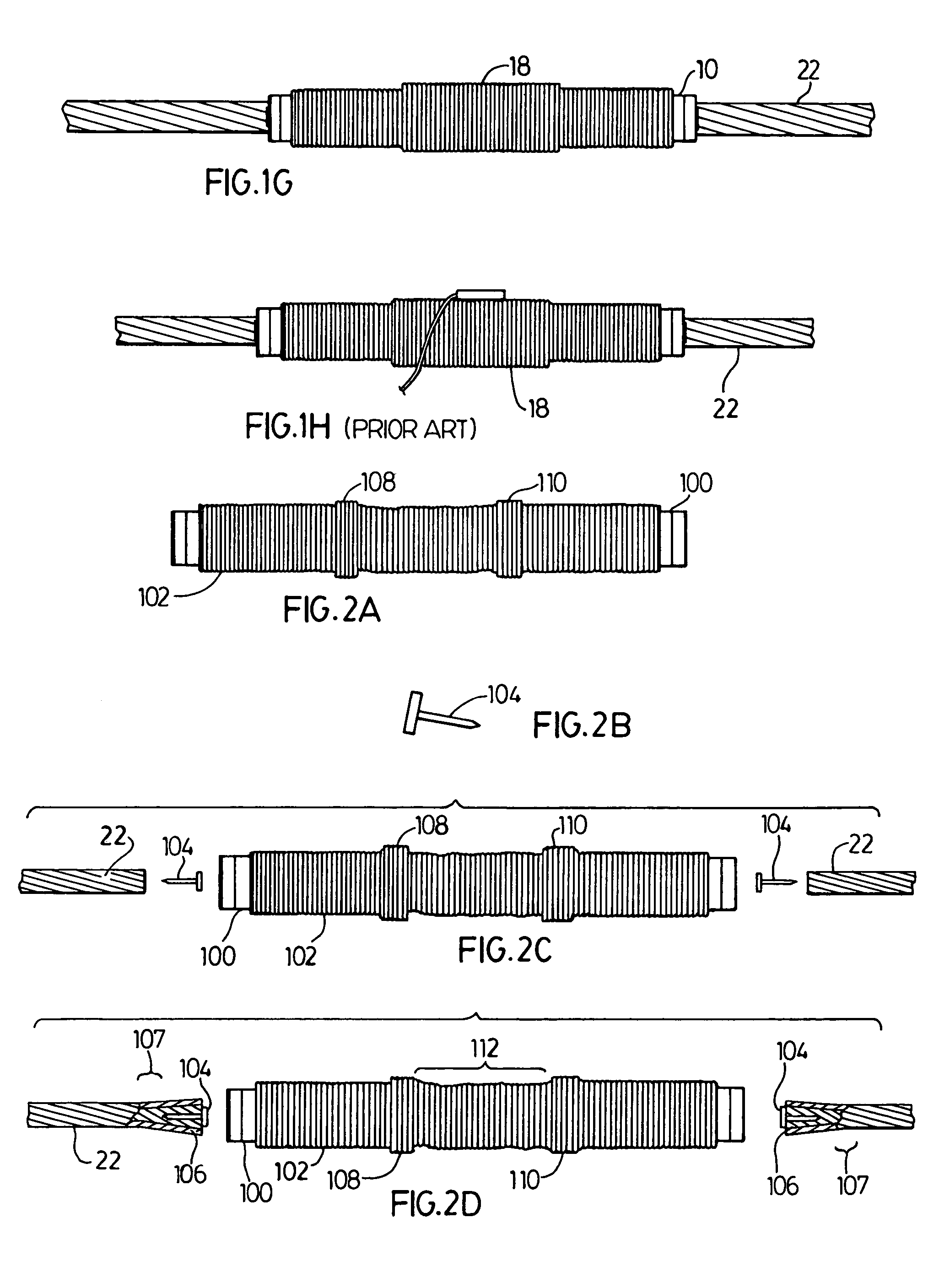
[0035]With reference to FIGS. 1A and 1B, a conductor splice consists of (a) an outer aluminum cylindrical sleeve (10) having a pre-mounted implosive charge layer (12) coiled around the outer surface (16) of connector (10). Layer (12) is of uniform thickness essentially the length of surface (16) except at a thicker central portion (18) (FIG. 1A); and (b) an inner steel sleeve (20) having an aluminum filter tube (not shown) on the outside (FIG. 1B).

[0036]Operational guidance as given to operators in the field follows with reference to FIGS. 1C-1H.[0037]1. Cut conductors (22) as cleanly as possible and minimize burring or bending aluminum strands (24). Cut steel strands (26) at a distance of half the length of inner steel sleeve (20) less 0.1 in. (2-3mm). Rewind any loose steel strands and bind securely with wire. (FIG. 1C).[0038]2. Mark each end of conductors (22) at a distance of half the length of outer aluminum sleeve (10) less 0.1 (2-3mm). (FIG. 1D).[0039]3. Slide the combined ch...


PUM

PropertyMeasurementUnit
diameteraaaaaaaaaa
lengthaaaaaaaaaa
diameteraaaaaaaaaa

Abstract

A method of joining the interfacing ends of cables, one to another, wherein each comprises a plurality of conductor strands, comprising (i) providing each of the ends with an enlarged terminal portion of greater diameter than the cable adjacent the end, (ii) inserting the ends into a connecting tube having an outer layer of an explosive charge, and (iii) detonating the explosive layer so as to compress the connecting tube around the conductor strands. The method offers a cheaper, faster and simpler method of joining a bundle of wires and the like than prior art methods.

Description

FIELD OF THE INVENTION[0001]The present invention relates to a method for joining wires, rods, cables, high tension lines and the like and for attaching an end fastener thereto, by means of an explosive charge; to said fastener for use in said method, and to a joined wire fastener combination when made by said process.BACKGROUND OF THE INVENTION[0002]In connection with heavy gauge wires, which may be disposed in positions which are difficult to reach, commensurately high powered tools are required to make pressure connections between said wires. In view of the weight and bulk of the tools it may be inconvenient or impossible to carry such tools to the sites at which the joining is to be made.[0003]It has previously been proposed to connect ends of wires and the like by inserting the ends into a corresponding bore of a connecting member provided with an external layer of explosive, which during detonation, compresses the connecting member around the ends. The layer of explosive used ...

Claims


Application Information

Patent Timeline
Patent Type & Authority Patents(United States)
IPC IPC(8): H01R43/00H01R4/08H01R4/50H01R4/62H01R11/09H01R43/027H01R43/042
CPCH01R4/08H01R43/0422H01R4/5033H01R4/62H01R11/09H01R43/0275Y10T29/49195Y10T29/53243Y10T29/49194Y10T29/49202Y10T29/53217Y10T29/49199
Inventor PASINI, CIRO
Owner HUBBELL INC
Why Eureka
Try Eureka