Automatic sampler

a sampler and automatic technology, applied in the field of automatic samplers, can solve the problems of reducing the mechanical strength of the sampler, reducing prone to buckling or the like of the needle, so as to improve the accuracy of analysis, reduce the amount of cross-contamination, and increase the accuracy of calculation

Active Publication Date: 2007-05-22
SHIMADZU CORP
View PDF3 Cites 16 Cited by
  • Summary
  • Abstract
  • Description
  • Claims
  • Application Information

AI Technical Summary

Benefits of technology

[0019]Conventionally, the outer diameter of the tip end of a conventional needle has been 0.65 mm or larger. In the automatic sampler according to the present invention, however, the outer diameter of the tip end of the needle is smaller, i.e., 0.6 mm at most, and 0.1 mm at the least. Thus, the contact area between the outer surface of the needle tip, which is inserted into the injection port's insertion hole, and the inner surface of the injection port's insertion hole is reduced. This reduces the absolute amount of the liquid sample transferred from the outer surface of the needle to the inner surface of the injection port's insertion hole, i.e., the amount adhering to the inner surface, when introducing the liquid sample via the injection port. As a result, the amount of cross-contamination can be reduced relative to that of a conventional automatic sampler.
[0020]For example, the automatic sampler of the present invention employed in a liquid chromatograph prevents the peak derived from a component in a previous sample from appearing in the chromatogram. Even if the peak did appear to some extent, the peak intensity would be reduced relative to that in a conventional sampler. This increases the accuracy in calculating peak heights and peak areas of object components, thereby improving the accuracy of analyses. In addition, components found only in trace amounts, which have been conventionally undetectable due to cross-contamination, can be detected, thereby improving analysis sensitivity.
[0021]When the outer diameter of the needle tip is reduced, however, its mechanical strength is also reduced, thereby rendering the needle susceptible to buckling or the like during insertion. In the automatic sampler in the present invention, therefore, it is preferable to reduce the pressure applied during the insertion of the needle into the injection port's insertion hole from the conventional 4 kg, to 3 kg or less.
[0022]The aforementioned reduction in the contact area between the outer surface of the needle tip and the inner surface of the injection port's insertion hole also reduces the frictional force experienced during the needle insertion. Thus, even when the pressure is reduced, the needle can be pressed into the insertion hole sufficiently deep enough to ensure fluid-tightness, thereby preventing buckling or deformation of the needle.

Problems solved by technology

When the outer diameter of the needle tip is reduced, however, its mechanical strength is also reduced, thereby rendering the needle susceptible to buckling or the like during insertion.

Method used


Image

  • Automatic sampler
  • Automatic sampler
  • Automatic sampler

Examples


Embodiment Construction

[0029]In the following description, embodiments of the present invention will be explained with reference to the associated drawings.

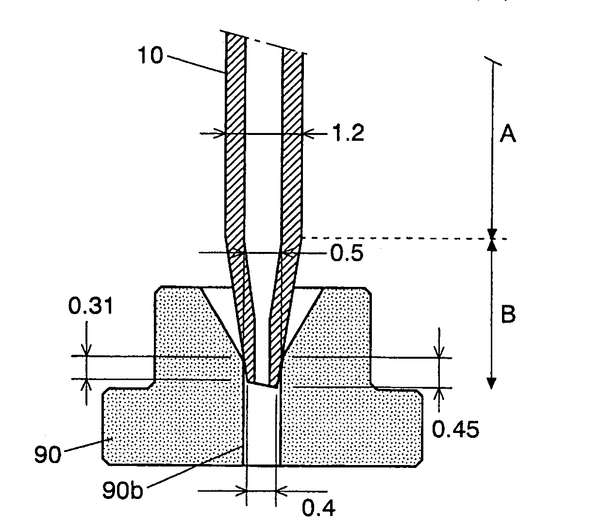
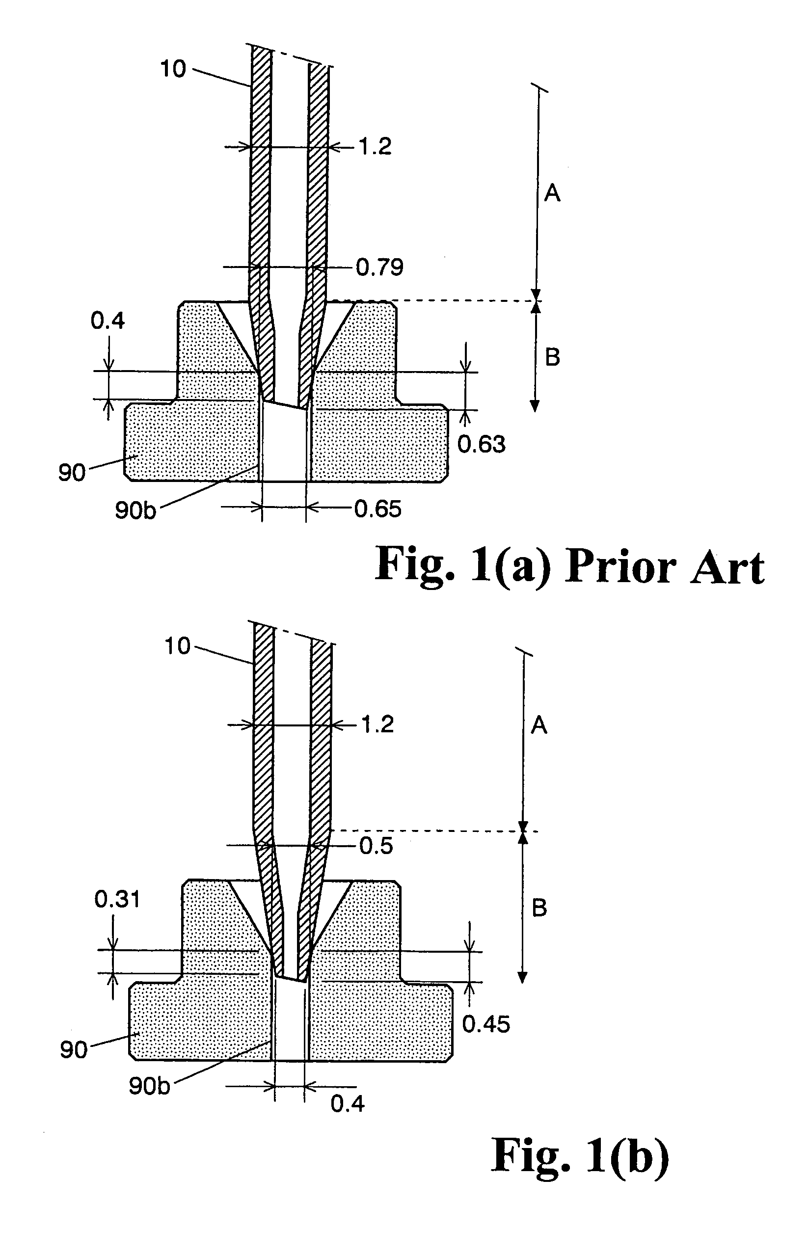
[0030]In the following, an automatic sampler according to one embodiment of the present invention will be explained with reference to FIGS. 1(a) and 1(b). FIGS. 1(a) and 1(b) are longitudinal sectional views showing the state where a needle 10 is inserted into an insertion hole 90b of a sealing member 90 of an injection port 9. FIG. 1(a) illustrates a conventional automatic sampler, and FIG. 1(b) illustrates an automatic sampler according to one embodiment of the present invention. In FIGS. 1(a) and 1(b), the dimensions are expressed in millimeters (mm).

[0031]The needle 10 and the sealing member 9 used in the conventional automatic sampler shown in FIG. 1(a) will be explained first. The outer and inner diameters of the straight section of the needle 10 indicated as “A” in FIG. 1(a) are 1.2 mm and 0.4 mm, respectively. The outer and inner diameters at t...


PUM

PropertyMeasurementUnit
outer diameteraaaaaaaaaa
outer diametersaaaaaaaaaa

Abstract

An automatic sampler for automatically sampling liquid samples to be introduced into apparatuses that analyze liquid samples, such as liquid chromatographs, includes a needle with a tapered tip end for suctioning and ejecting liquid, a mechanism for moving the needle in the horizontal and vertical directions, and an injection port having an insertion hole into which the tip end of the needle can be inserted. The outer diameter of the tip end of the needle is at least 0.1 mm and at most 0.6 mm. By reducing the needle-to-port contact area, the automatic sampler facilitates high-sensitivity and high-precision analyses by significantly reducing the amount of cross-contamination, regardless of the type of samples.

Description

BACKGROUND OF THE INVENTION AND RELATED ART STATEMENT[0001]The present invention relates to automatic samplers for automatically sampling liquid samples to be introduced into analytical apparatuses that analyze liquid samples, such as liquid chromatographs.[0002]In a liquid chromatograph, an automatic sampler is used in order to automatically select numerous samples to be introduced to columns. FIG. 3 is a schematic diagram showing the channel structure of a conventional automatic sampler used in a liquid chromatograph, as shown in Patent Reference 1.[0003]In the automatic sampler 3, the injection valve (high-pressure valve) 4 is a rotary six-port, two-position channel switching valve having six ports 4a–4f. Through a switching operation, two adjacent ports are selectively connected. In other words, the combinations of the two-port connections indicated by the solid or broken lines in FIG. 3 can be switched. The low-pressure valve 5 is a rotary seven-port, six-position valve having ...

Claims


Application Information

Patent Timeline
Patent Type & Authority Patents(United States)
IPC IPC(8): G01N1/22B01L3/02
CPCG01N30/24G01N35/1095
Inventor MAEDA, YOSHIAKI
Owner SHIMADZU CORP
Why Eureka
Try Eureka