Pneumatic tube system terminal and method
a technology of pneumatic tube and terminal, applied in the direction of conveyors, transportation and packaging, etc., can solve the problems of limiting the configuration options of service provider areas, limiting efficiency, and affecting the efficiency of the terminal
- Summary
- Abstract
- Description
- Claims
- Application Information
AI Technical Summary
Benefits of technology
Problems solved by technology
Method used
Image
Examples
Embodiment Construction
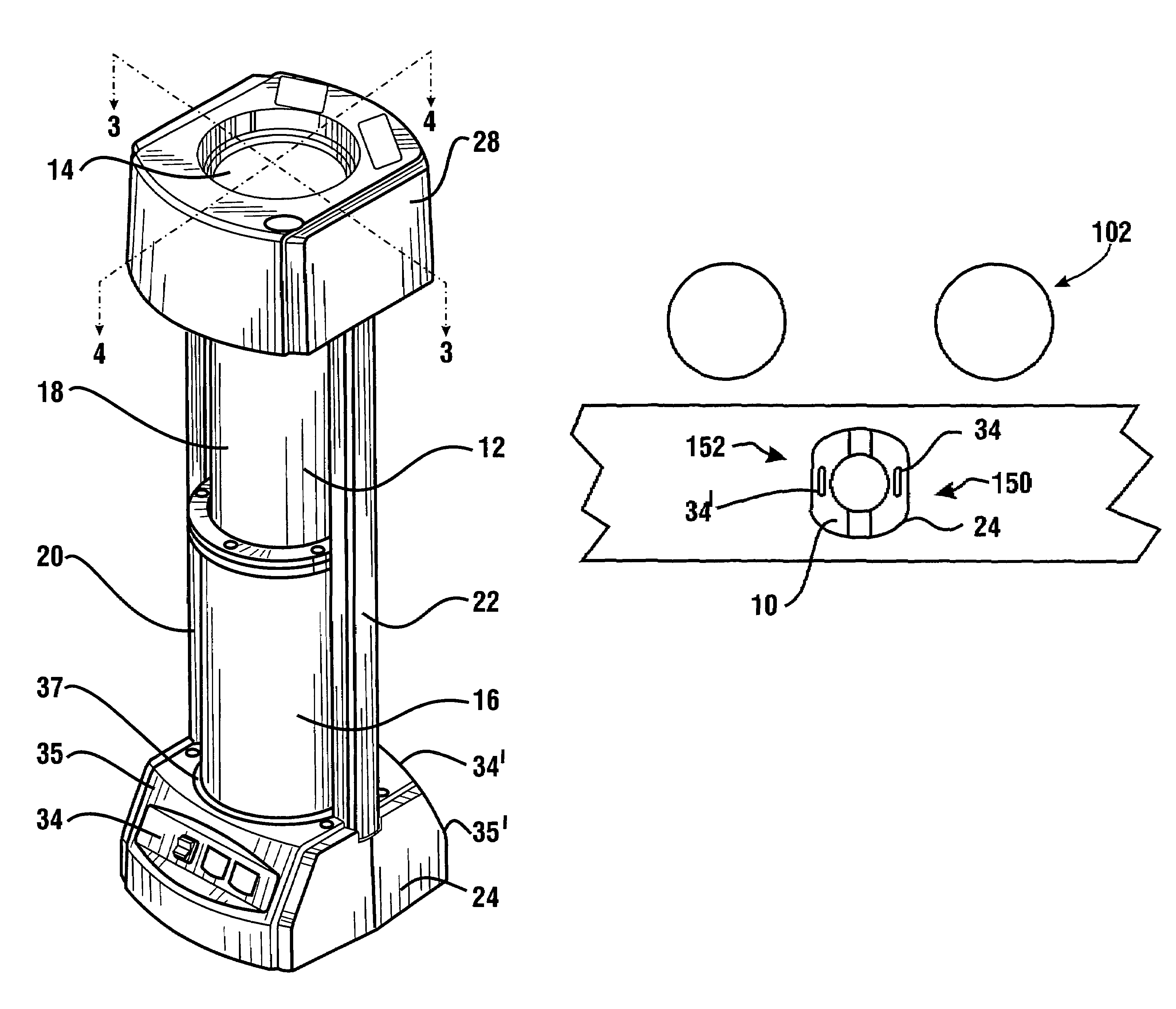
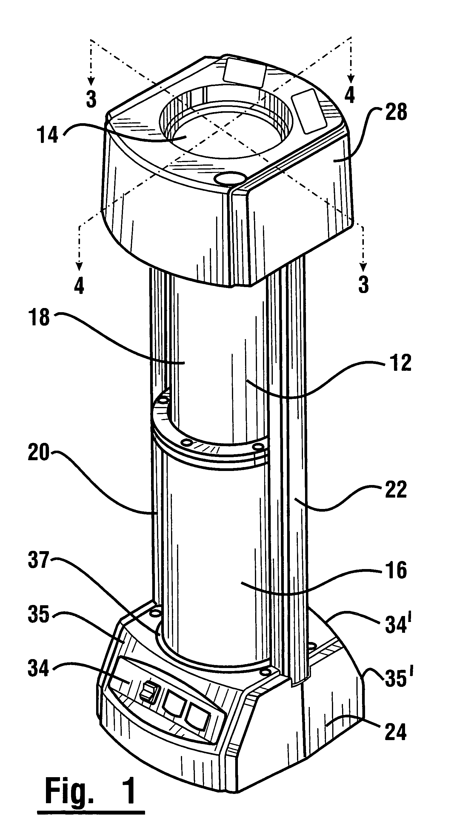
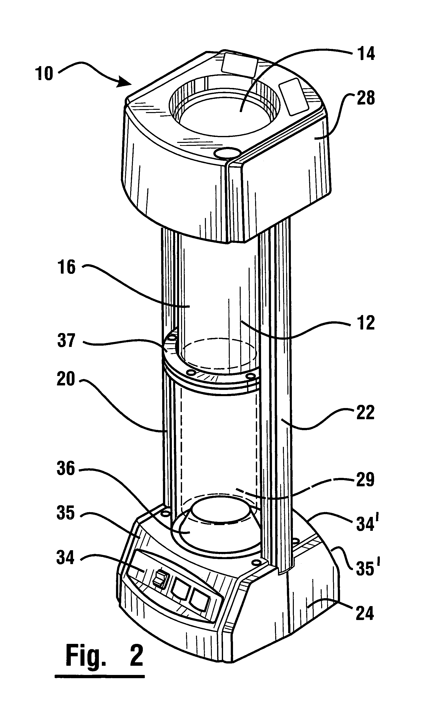
[0044]With reference to FIG. 1, there is shown an exemplary service provider user terminal 10 that is adapted to send and receive a carrier that is movable in response to air pressure through a transport tube as will be discussed in further detail below.
[0045]User terminal 10 includes a body 12 having an opening 14 therein through which a carrier may be sent and received. User terminal 10 includes a movable member 16 and a stationary upper member 18. In an exemplary embodiment both the movable member and stationary member are generally cylindrical. In other embodiments other configurations may be used.
[0046]In one exemplary embodiment, body 12 has in fixed supporting connection therewith first and second side rails 20, 22 extending vertically in disposed relation from a base 24. A cap member 28 is positioned adjacent first and second side rails 20, 22 at a position vertically disposed from base member 24.
[0047]Movable member 16 is operative to selectively move in a vertical directio...
PUM
 Abstract
Description
Claims
Application Information
 - R&D
- Intellectual Property
- Life Sciences
- Materials
- Tech Scout
- Unparalleled Data Quality
- Higher Quality Content
- 60% Fewer Hallucinations
Browse by: Latest US Patents, China's latest patents, Technical Efficacy Thesaurus, Application Domain, Technology Topic, Popular Technical Reports.
© 2025 PatSnap. All rights reserved.Legal|Privacy policy|Modern Slavery Act Transparency Statement|Sitemap|About US| Contact US: help@patsnap.com


