Methods and apparatus for intraluminal deposition of hydrogels

a technology of hydrogels and hydrogels, which is applied in the direction of catheters, blood vessels, pharmaceutical product forms, etc., can solve the problems of engendering a variety of symptoms and limited utility of the devices described in the foregoing referen

Inactive Publication Date: 2007-05-22
INCEPT LLC
View PDF62 Cites 191 Cited by
  • Summary
  • Abstract
  • Description
  • Claims
  • Application Information

AI Technical Summary

Benefits of technology

[0014]It is another object of this invention to provide methods and apparatus for using multi-component hydrogel systems as embolic materials to occlude arteriovenous malformations, thus taking advantage of the relative ease with which the crosslinkable components of a hydrogel system may be delivered.
[0015]It is a further object of the present invention to provide methods and apparatus for excluding aneurysms using hydrogels that are formed in situ, without partially or completely occluding the vessel.
[0017]In accordance with the present invention, delivery systems are provided for delivering separate prepolymer components of a hydrogel system, without premature crosslinking within the delivery system. In one embodiment, the delivery system includes an occlusive element for anchoring a distal end and isolating the region in which the hydrogel is to be formed in situ. In another embodiment, the delivery system may include variable stiffness regions to enable passage through tortuous anatomy. In yet another embodiment, the delivery system includes a steerable tip. In still further alternative embodiments, the prepolymer components of the hydrogel system may be mixed together in a mixing chamber disposed in a distal region of the delivery system, and then extruded into the body lumen or void during the crosslinking process, to reduce washout or dilution of the components.

Problems solved by technology

Because such hydrogels undergo a relatively small amount of swelling and are not absorbable, so that the sterilization is not reversible, the devices described in the foregoing reference have found limited utility.
An AVM may lead to a substantial diversion of blood from the intended tissue and may consequently engender a variety of symptoms, including those leading to morbidity.
Delivery of these embolic materials often requires the use of elaborate delivery systems.

Method used


Image

  • Methods and apparatus for intraluminal deposition of hydrogels
  • Methods and apparatus for intraluminal deposition of hydrogels
  • Methods and apparatus for intraluminal deposition of hydrogels

Examples


example 1

Preparation of a Metered Liquid Embolic

[0073]Previously known treatments for embolization all basically rely on blood flow in one form or another to either react to the material or to carry it downstream to a geometric constraint, such as a tapered portion of a vessel. A drawback of this approach, however, is that it is difficult to form a short site-specific occlusive plug.

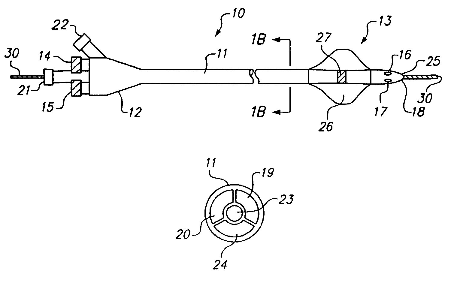
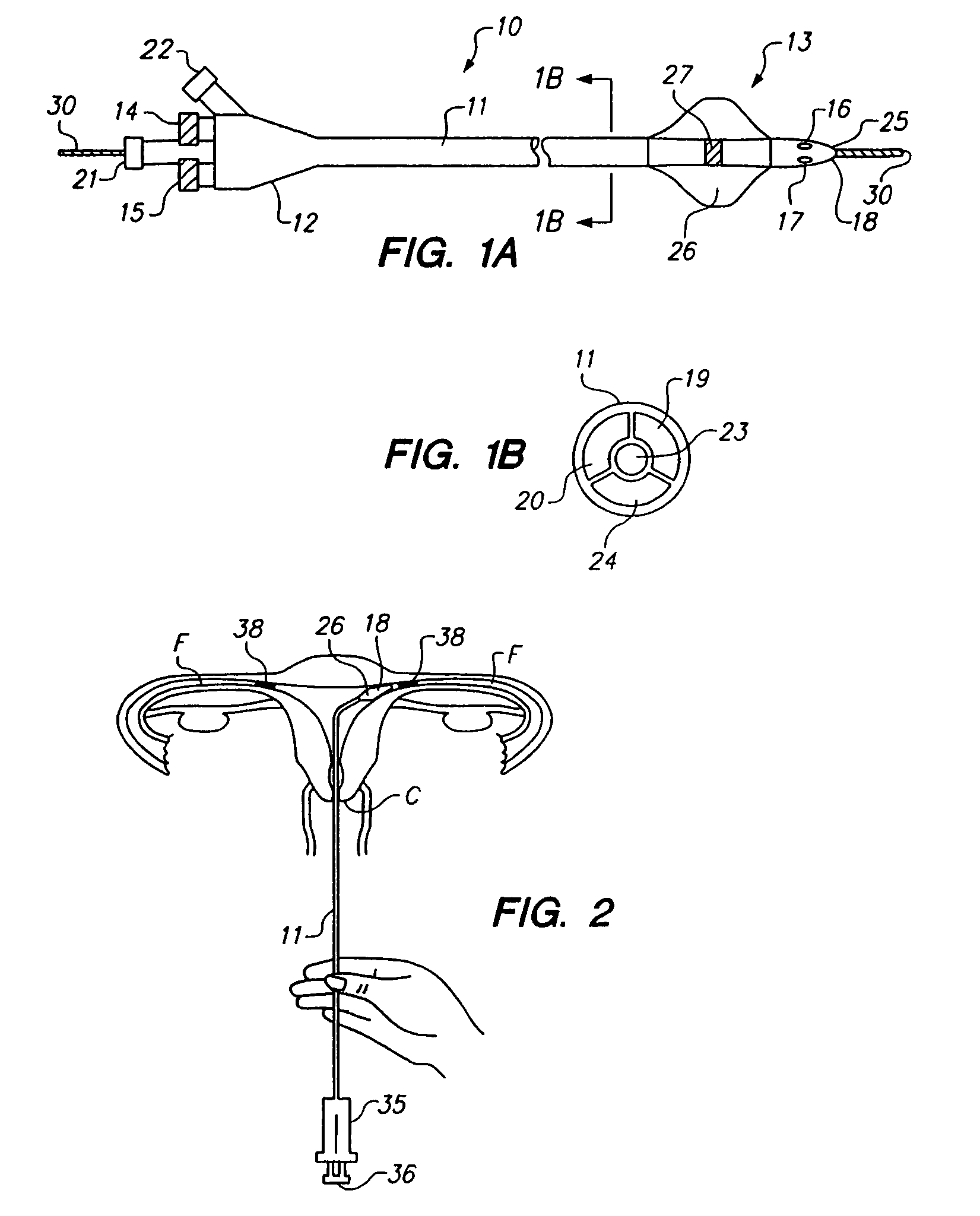
[0074]Numerous instances where it is desirable to form a discrete “plug” to block a specific region of a vessel or a specific side-branch, for example, to treat an arterio-venous fistula (AVF) or patent ductus arteriosus (PDA). A desirable configuration would have the ability to deploy a plug in a controlled manner even in the presence of blood flow to cause embolization of the vascular defect, but low risk of accidental embolization of other downstream structures. Physically, such materials could be delivered via a screw-driven syringe handle that allows the two materials not only to be delivered equally, but al...

example 2

Preparation of a Diffusely Polymerizing Liquid Embolic

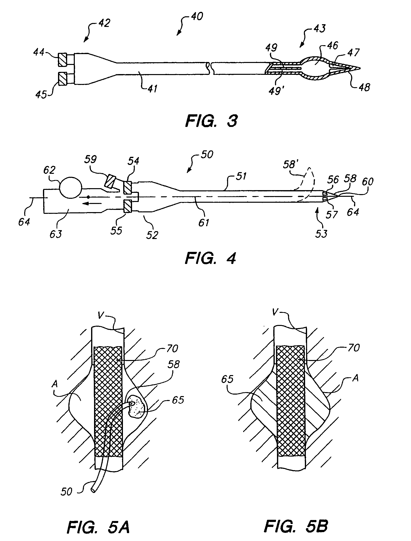
[0080]Occasionally a need arises for a more diffuse, deeper-reaching liquid embolic that is capable of flowing for some distance within the vasculature. The system described in this example 2 allows deep introduction of liquid embolic materials before curing and may be especially useful in treating hypervascular tumors (among other such diffuse vascular diseases, including arterio venous malformations), where it is necessary to infuse the materials as deep as possible into the tumor vasculature, thereby embolizing all of collateral and side-branches of the effected vasculature.

[0081]In this example 2, a combination of slower polymerization and lower material viscosities is provided, consisting of two PEG di-acrylate (20% 3.35 da) solutions in water with 3000 ppm hydrogen peroxide and 2% Ferrous gluconate as solutions A and B, respectively, with a 30% metrizamide concentration in each solution as a radiopacifying agent. The time f...

example 3

Preparation of a Bio-Resorbable Liquid Embolic

[0084]In many instances, such as arterio-venous malformations (“AVM”) or aneurysm, permanent occlusion of the defect is required. However, in other situations, permanent embolization may not be desirable. This may occur, for example, if one needs to re-visit a partially occluded tumor bed for further therapy. Previously known treatment modalities for hyper-vascular tumor embolization, with such materials as cyanoacrylate materials and small particle PVA, form a permanent “implant” that is either a hard polymeric branched implant or a plurality of small particles inhibiting flow by hitting a geometric restraint such as a tapered vessel diameter.

[0085]Because it may be necessary, however, to re-access the vessels of the tumor after they have been embolized, in case small collaterals have formed or side-branches had not been adequately embolized. With the previously known treatment modalities, it would be virtually impossible to re-canalize...


PUM


Abstract

Methods and apparatus of forming hydrogel systems in situ are provided using a delivery system configured to deliver two or more fluent prepolymer solutions without premature crosslinking. The delivery system comprises separate first and second lumens coupling first and second inlet ports and first and second outlet ports, respectively, and may include a balloon, flexible distal region, mixing chamber or steerable distal end. Multi-component hydrogel systems suitable for use with the inventive methods and apparatus are also described.

Description

RELATED APPLICATIONS[0001]This application is a continuation of U.S. patent application Ser. No. 09 / 990,883, filed Nov. 21, 2001, now issued as U.S. Pat. No. 6,689,148, which is a continuation of U.S. patent application Ser. No. 09 / 390,046 filed Sep. 3, 1999, now issued as U.S. Pat. No. 6,379,373, which is a Continuation-In-Part of U.S. patent application Ser. No. 09 / 133,950 filed Aug. 14, 1998, now issued as U.S. Pat. No. 6,152,943, which are hereby incorporated by reference herein.FIELD OF THE INVENTION[0002]This present invention relates to methods and apparatus for applying hydrogels within body lumens to occlude, coat or support tissue. More particularly, the present invention relates apparatus and methods for intraluminally delivering two or more liquid components to form a hydrogel implant in situ.BACKGROUND OF THE INVENTION[0003]Hydrogels are materials that absorb solvents (such as water), undergo rapid swelling without discernible dissolution, and maintain three-dimensional...

Claims


Application Information

Patent Timeline
Patent Type & Authority Patents(United States)
IPC IPC(8): A61M29/00A61J3/00A61B17/00A61B17/12A61F6/22A61M25/00A61M25/01A61M31/00
CPCA61B17/12022A61B17/12109A61B17/12118A61B17/12136A61B17/12186A61B17/1219A61F2/07A61F6/225A61K9/0024A61L24/001A61L24/0031A61L31/146A61M25/10A61M31/00A61M31/005A61B17/12099A61F2/90A61B2017/00495A61F2002/077A61L2430/36A61M2025/0057A61M2210/1425
Inventor SAWHNEY, AMARPREET S.SPIRIDIGLIOZZI, JOHN
Owner INCEPT LLC
Why Eureka
Try Eureka