Reed mount for woodwind mouthpiece

a technology for woodwind mouthpieces and reeds, which is applied in the field of woodwind mouthpieces, can solve problems such as slippage and deficiencies of ligatures, and achieve the effect of improving the means of attaching reeds, and being easily and quickly installed

Active Publication Date: 2007-05-22
BRONEN ANDREW
View PDF51 Cites 20 Cited by
  • Summary
  • Abstract
  • Description
  • Claims
  • Application Information

AI Technical Summary

Benefits of technology

[0009]The present invention provides a unique configuration for a reed and mouthpiece assembly which when utilized together provide an improved means for the attaching of a reed with respect to a woodwind instrument mouthpiece, and which can easily and quickly be installed. A preferred embodiment of the design does not require use of any special reed, or modifications thereof.

Problems solved by technology

Traditional ligatures have known deficiencies, including slippage, especially with changes in temperature and breath-induced moisture.

Method used


Image

  • Reed mount for woodwind mouthpiece
  • Reed mount for woodwind mouthpiece
  • Reed mount for woodwind mouthpiece

Examples


first embodiment

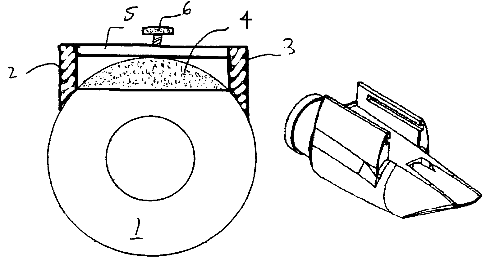
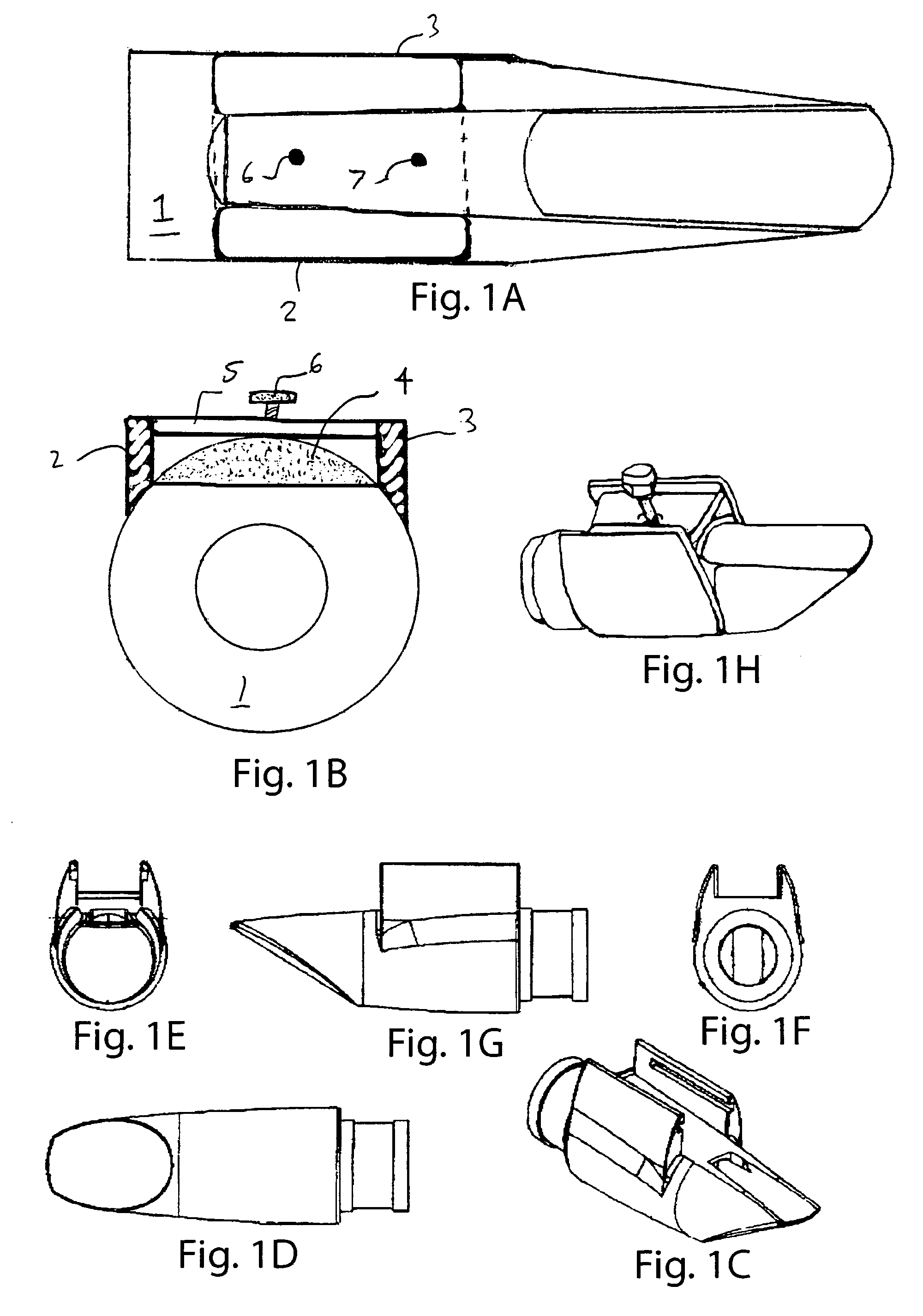
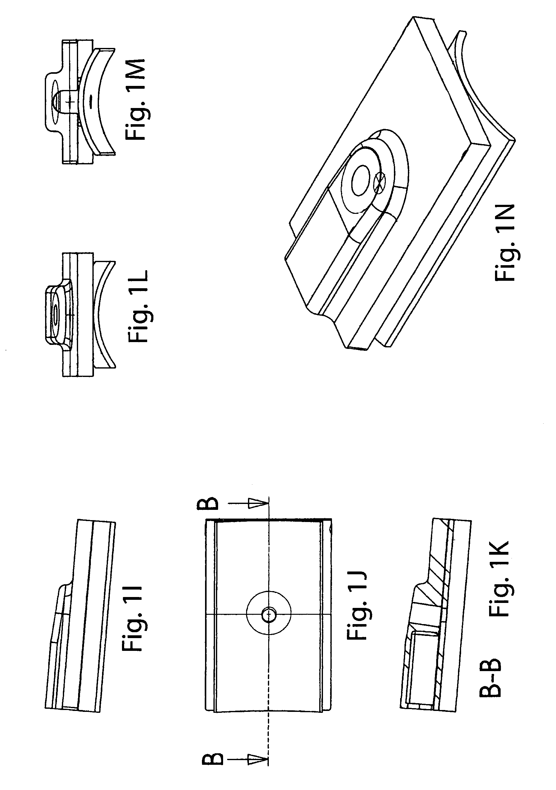
[0035]FIG. 1A shows the invention, in which the body 1 of the mouthpiece has a pair of vertical columns 2, 3, which extend from the lower side of the body 1, at the based of the reed 4. A retention plate 5 is held in fixed position by the pair of vertical columns 2, 3 over the base of the reed 4. A pair of screws 6, 7 are threaded through the retention plate 4, and apply a direct radial force on the reed. As shown in FIGS. 1H–1N, a single screw may also be used. The tip of the screw(s) may have a conformal plate or other structure, not shown in FIGS. 1A and 1B, but shown in FIGS. 1I–1N, to distribute the applied forces over the base of the reed 4.

[0036]The mouthpiece 1 preferably has a stop 40 slightly beyond the end of a normal reed, which defines a constrained space for inserting the reed, while being prevented from falling out the back. It is also possible to precisely align this stop to perfectly position the reed; however, due to manufacturing and style variations in reeds, an ...

second embodiment

[0037]FIGS. 2A and 2B show the invention, in which the retention plate 5 and pair of screws 6, 7 are replaced with a pair of cam actuators 8, 9. The cam actuators 8, 9 are affixed directly to the vertical columns 2, 3, and can be adjusted to achieve a desired radial force on the base of the reed 4.

[0038]FIGS. 3A, 3B, 3C, and 3D show a slight variation on the embodiment of FIGS. 1A, 1B and 1C. In this case, the vertical columns 2, 3 are channeled with grooves 13, 14, as shown in FIG. 3C. The retention plate 5 has complementary tongues 11, 12 which conform to the shape of the grooves 13, 14, allowing it to be removed. FIG. 3D shows the conformal plate 10, which is adjusted by the action of screw 6 to apply a varying pressure on the base of the reed 4. The screw 6 is connected to the conformal plate 10 by a bearing 15.

[0039]FIGS. 4A, 4B, 4C, and 4D show an embodiment similar to that shown in FIGS. 3A, 3B, 3C, and 3D. In this case, a knurled disk 24, having a center threaded hole for th...


PUM


Abstract

A mouthpiece assembly for a woodwind musical instrument comprising a mouthpiece body defining an air conduit extending therethrough, a reed placement surface defined on the mouthpiece body adjacent said air conduit, a pair of extensions, integral to and extending from the body of the mouthpiece on opposed sides of the reed placement surface with respect to an opening of the air conduit, and a mechanism for selectively applying a compressive force to a reed placed over the opening of the air conduit, with respect to the body of the mouthpiece, generating to a tensile force applied to each of said pair of extensions, to selectively retain the reed in position. The present design provides advantageous acoustic properties for the mouthpiece, and further provides for advantageous placement of an electronic pickup for receiving the output of the instrument.

Description

FIELD OF THE INVENTION[0001]The present invention relates to the field of woodwind mouthpieces, and more particularly, to an improved system and method for mounting a reed to a woodwind mouthpiece.BACKGROUND OF THE INVENTION[0002]Traditional woodwind instrument mouthpieces comprise a body, a ligature, and a reed. The body, which is typically made of plastic, rubber or metal, has a smooth upper surface which is intended to rest against the upper lip and teeth, and a lower surface which is intended to mount the reed, which has a small gap from the body, allowing flowing air to vibrate the reed and produce a tone, whose frequency is generally controlled by the remainder of the instrument. The player may also control the reed by applying pressure with the lip and teeth.[0003]Various configurations have been designed for mouthpieces and reeds for musical instruments, usually woodwind instruments, such as shown in U.S. Pat. No. 147,202 patented Feb. 3, 1874 to C. W. Vogel on “Reed-Organs”...

Claims


Application Information

Patent Timeline
Patent Type & Authority Patents(United States)
IPC IPC(8): G10D9/02
CPCG10D9/02G10D7/08
Inventor BRONEN, ANDREW
Owner BRONEN ANDREW
Why Eureka
Try Eureka