Battery container for an electric vehicle

a battery container and electric vehicle technology, applied in the field of electric vehicles, can solve the problems of shortening the charging time and saving the labor of conveying, and achieve the effects of less limited, convenient charging, and convenient us

Inactive Publication Date: 2007-05-22
CHEN YUNG CHENG
View PDF12 Cites 24 Cited by
  • Summary
  • Abstract
  • Description
  • Claims
  • Application Information

AI Technical Summary

Benefits of technology

[0009]Through this specially improved structure design, the battery container of an electric vehicle can be easily detached from the vehicle for the charge of power, which makes the charge time-saving and convenient, as well as less limited by space constraints, and consequently more practical and easier to use.
[0010]As its structural features, the battery container is composed of two cases, which are aligned and combined together. It can be divided into two groups for independent charge, which greatly shortens the charging time and saves the labor to convey it.
[0012]The structure design of the positioning structure, as composed of a fixed base 20, a positioning board 30 and a retractable spring 40, is simple and advantageous for mass production, and is quite practical and convenient in that the battery container can be released just by a simple pulling action.

Problems solved by technology

It can be divided into two groups for independent charge, which greatly shortens the charging time and saves the labor to convey it.

Method used


Image

  • Battery container for an electric vehicle
  • Battery container for an electric vehicle
  • Battery container for an electric vehicle

Examples


Embodiment Construction

[0021]The features and the advantages of the present invention will be more readily understood upon a thoughtful deliberation of the following detailed description of a preferred embodiment of the present invention with reference to the accompanying drawings.

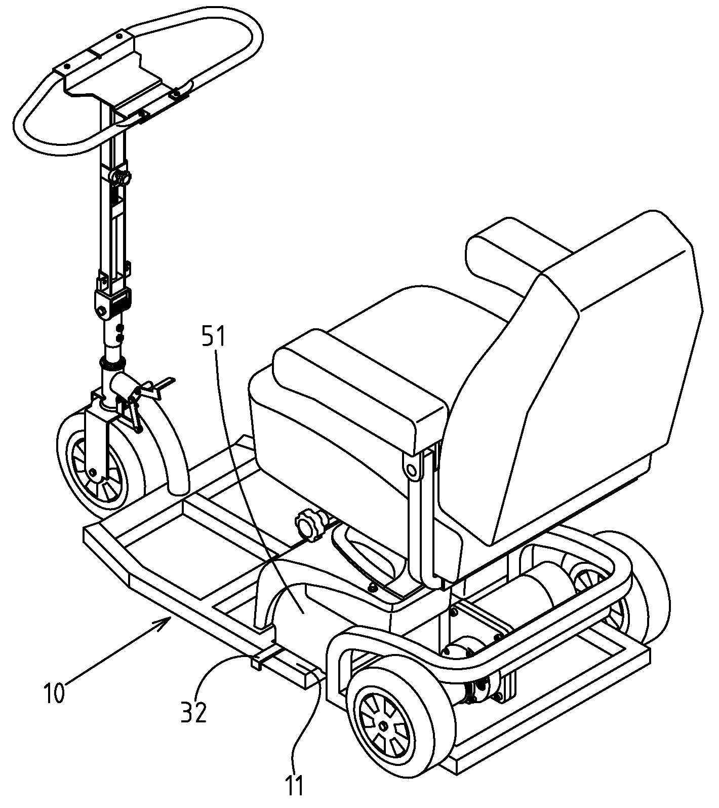
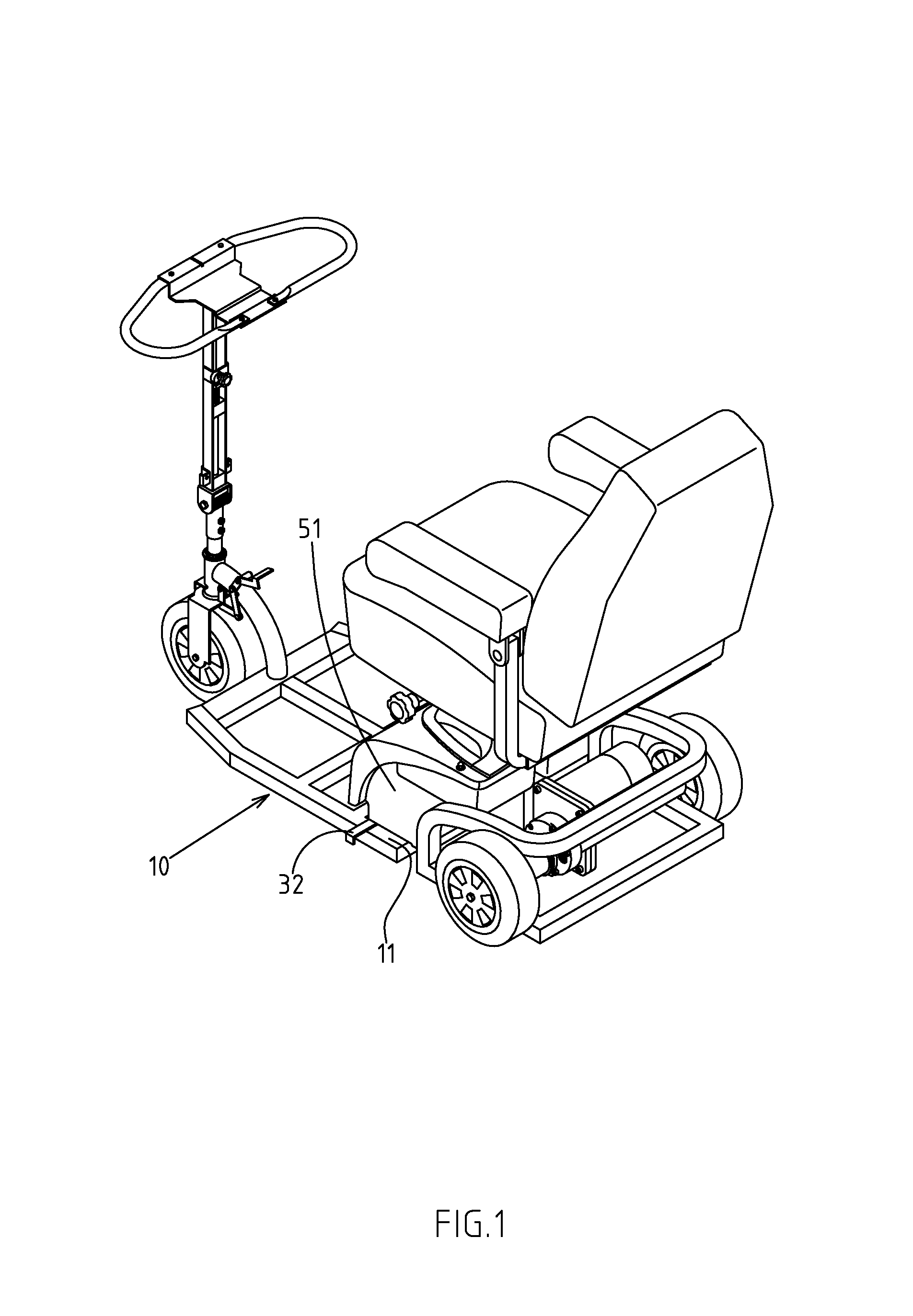
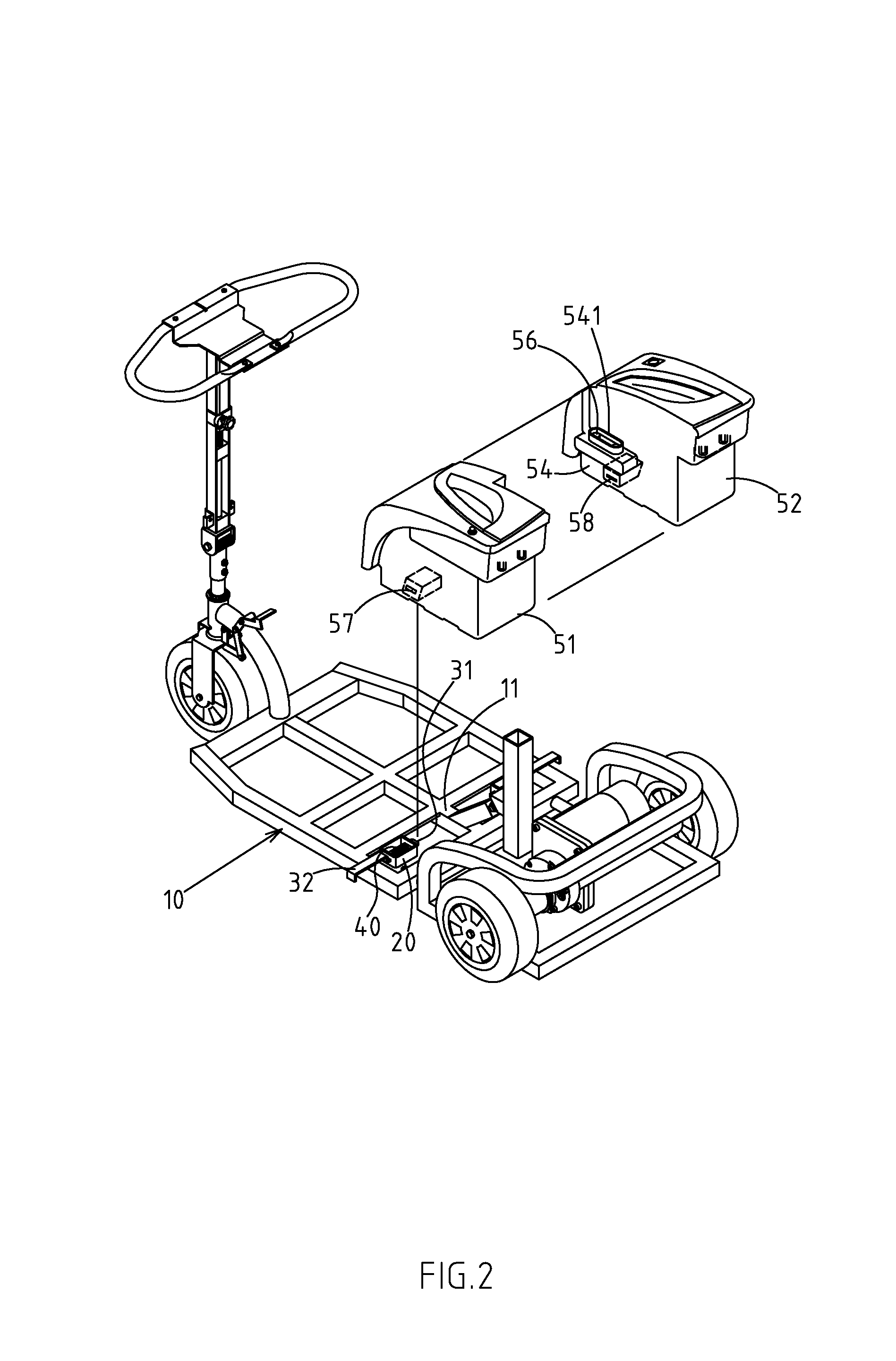
[0022]As shown in FIGS. 1–5, there is an improved battery container for an electric vehicle embodied in the present invention.

[0023]The present invention includes the electric vehicle body 10.

[0024]There is also a battery container supporting stand 11, which is installed at the preset site of the electric vehicle body 10 and forms a shape of a supporting surface.

[0025]There is a positioning structure, which is assembled on the left and right sides of the battery container supporting stand 11 of the battery container. Each assembly of the positioning structure includes: a fixed base 20, which provides a guiding runner 21; a positioning board 30, whose interior is pivoted to go through the center of the above guiding runner 21 and...


PUM

PropertyMeasurementUnit
chargeable electrical poweraaaaaaaaaa
timeaaaaaaaaaa
internal structuresaaaaaaaaaa

Abstract

A battery container of an electric vehicle is installed on the battery container supporting stand of the electric vehicle body. The container is a composite type and formed through alignment and combination of first and second cases. There are connecting ports, mutually embedded and mounted, on the assembled sides of these cases. The connecting ports have positive and negative electric connectors that can be oppositely inserted and jointed. The electrodes of the batteries inside the two cases can be connected. The battery container supporting stand forms a shape of a supporting surface. To ensure that the cases are placed together on the battery container supporting stand after alignment and combination, the assemblies of the positioning structure are used to control the positioning of and detachment between the battery container supporting stand and the cases. The battery container of an electric vehicle can be easily detached for independent charge.

Description

RELATED U.S. APPLICATIONS[0001]Not applicable.STATEMENT REGARDING FEDERALLY SPONSORED RESEARCH OR DEVELOPMENT[0002]Not applicable.REFERENCE TO MICROFICHE APPENDIX[0003]Not applicable.FIELD OF THE INVENTION[0004]The present invention relates generally to an electric vehicle, particularly to an electric vehicle having a battery container of a combined type and formed by the alignment and combination of two cases, which are then placed and fixed on the top of the electric vehicle's battery container supporting stand.BACKGROUND OF THE INVENTION[0005]It has been noted that the battery container of a conventional electric vehicle is usually contained and placed in the preset fixed slot on the vehicle body. To charge the battery, it is required to move the electric vehicle to the place closest to the location providing chargeable electrical power, and then through the connection by a charge cord, the task of power charge can be accomplished. However, due to different living environment, el...

Claims


Application Information

Patent Timeline
Patent Type & Authority Patents(United States)
IPC IPC(8): B60B33/06A61G5/04B60L9/02B60L11/18B62K5/00H01M50/204H01M50/244H01M50/249H01M50/262H01M50/296
CPCB60L11/1822B62K5/025H01M2/1077Y02T90/14Y02T10/7072Y02T90/124Y02T10/7005B60L53/80B60L50/64Y02T10/70Y02E60/10H01M50/204H01M50/249H01M50/296H01M50/262H01M50/244Y02T90/12
Inventor CHEN, YUNG CHENG
Owner CHEN YUNG CHENG
Why Eureka
Try Eureka