
System and method for computing the signal propagation time and the clock correction for mobile stations in a wireless network

Active Publication Date: 2007-05-22
ARRIS ENTERPRISES LLC
View PDF127 Cites 48 Cited by
  • Summary
  • Abstract
  • Description
  • Claims
  • Application Information

AI Technical Summary

Benefits of technology

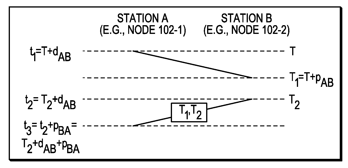
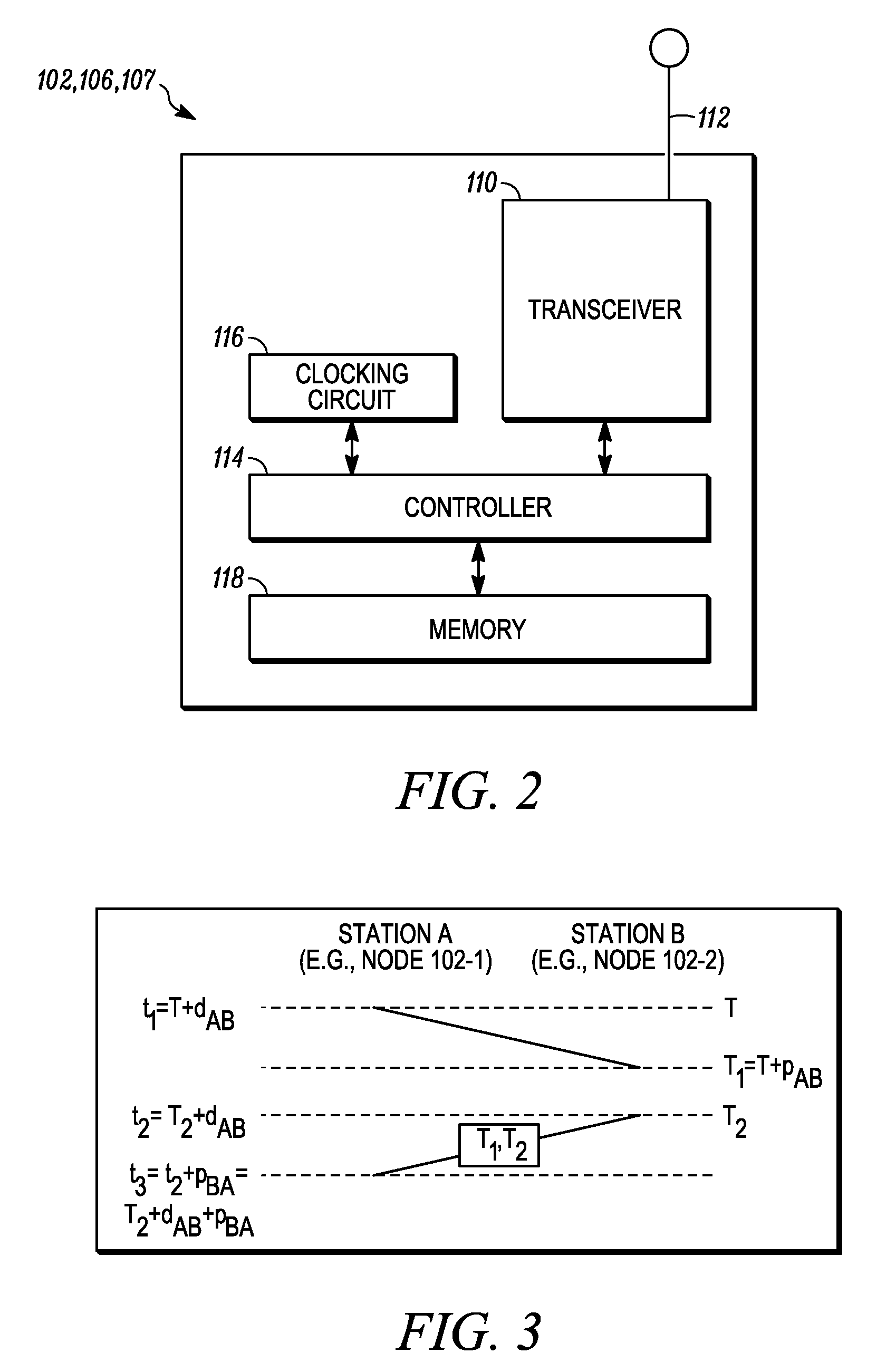
[0010]An object of the present invention is to enable a node, such as a mobile user terminal in a wireless communications network, to effectively and efficiently determine a clock correction factor for its local clock relative to a local clock of at least one other node, and well as the signal propagation time between itself and the other node.
[0011]Another object of the present invention relates to a system and method for enabling nodes in an ad-hoc packet-switched communications network to calculate their respective local clock correction factors relative to the local clocks of their neighboring nodes with minimal message transmissions between the nodes, to reduce the amount of overhead in the network needed for such clock correcting operations.

Problems solved by technology

However, since each mobile node has a local clock that is not necessarily in synchronization with the local clocks running on other nodes in the network, the propagation times for signals propagating between the node and the other nodes cannot typically be measured directly.
However, differences in the local clock times of neighboring nodes can result in multiple nodes attempting to transmit data packets during the same time slice, which can result in collisions between the data packets and thus, data packets can possibly be lost.
Also, although the local clocks of certain nodes may at one time be synchronized, a phenomenon known as clock drift can occur which can cause the local clock of a node to become unsynchronized with the local clocks of neighboring nodes.

Method used


Image

  • System and method for computing the signal propagation time and the clock correction for mobile stations in a wireless network
  • System and method for computing the signal propagation time and the clock correction for mobile stations in a wireless network
  • System and method for computing the signal propagation time and the clock correction for mobile stations in a wireless network

Examples


Embodiment Construction

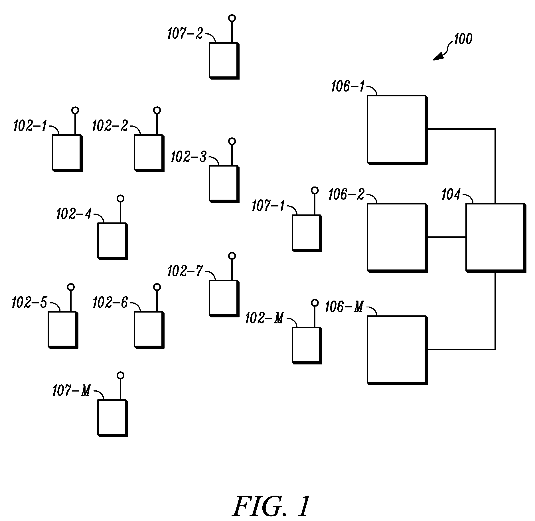
[0018]FIG. 1 is a block diagram illustrating an example of an ad-hoc packet-switched wireless communications network 100 employing an embodiment of the present invention. Specifically, the network 100 includes a plurality of mobile wireless user terminals 102-1 through 102-n (referred to generally as user terminals 102), and a fixed network 104 having a plurality of intelligent access points (IAPs) 106-1, 106-2, . . . , 106-n, for providing the user terminals 102 with access to the fixed network 104. The fixed network 104 includes, for example, a core local access network (LAN), and a plurality of servers and gateway routers, to thus provide the user terminals 102 with access to other networks, such as the public switched telephone network (PSTN) and the Internet.

[0019]The network 100 further includes fixed wireless routers 107-1 through 107-n, which act as routers for the user terminals 102-1 through 102-n and IAPs 106-1 through 106-n. The user terminals 102, IAPs 106 and fixed wir...


PUM


Abstract

A system and method for enabling a node, such as a mobile user terminal in a wireless communications network, such as an ad-hoc network, to effectively and efficiently determine a clock correction factor for its local clock relative to a local clock of at least one other node. The node calculates a difference between the timing of the local clock of the node and the local clock of the other node based on the timing of signals transmitted between the node and the other node, and information pertaining to the transmission and reception of these signals by the node and the other node as indicated by the respective local clocks of the node and the other node. The system and method further enables a plurality of nodes in an ad-hoc packet-switched communications network to calculate their respective local clock correction factors relative to the local clocks of their neighboring nodes in this manner with minimal message transmissions between the nodes, to reduce the amount of overhead in the network needed for such clock correcting operations.

Description

BACKGROUND OF THE INVENTION[0001]1. Field of the Invention[0002]The present invention relates to a system and method for enabling a node, such as a mobile user terminal in a wireless communications network, to determine a clock correction factor for its local clock relative to a local clock of at least one other node, as well as a signal propagation time between the node and the other node, based on the timing of signals transmitted between the node and the other node, and clock information received from the other node, so that the node can use the clock correction factor when calculating its distance to the other node. More particularly, the present invention relates to a system and method for enabling nodes in an ad-hoc packet-switched communications network to calculate their respective local clock correction factors relative to the local clocks of their neighboring nodes with minimal message transmissions between the nodes, to reduce the amount of overhead in the network needed ...

Claims


Application Information

Patent Timeline
IPC IPC(8): H04J3/06
CPCH04J3/0667H04W56/001H04W84/18
Inventor BELCEA, JOHN M.
Owner ARRIS ENTERPRISES LLC
Learn More