
Video stabilizer

a stabilizer and video technology, applied in the field of digital image processing, can solve the problems of unwanted motion, unfavorable eye sensation, and unwanted motion of video cameras,

Inactive Publication Date: 2007-05-22
ARCSOFT
View PDF4 Cites 23 Cited by
  • Summary
  • Abstract
  • Description
  • Claims
  • Application Information

AI Technical Summary

Benefits of technology

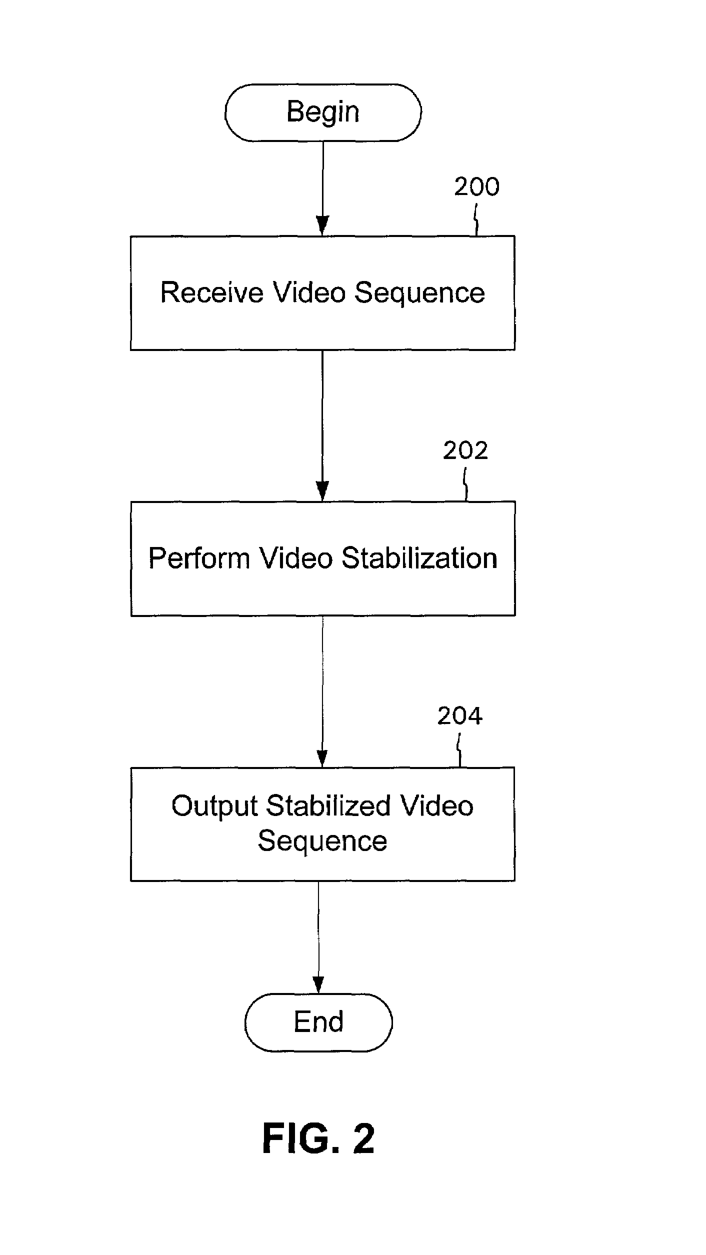
[0014]According to one embodiment of the invention, a method for stabilizing motion in a sequence of frames is provided. One or more features in a first frame in the sequence of frames are identified. Tracked positions are calculated for one or more features in each other frame in the sequence of frames based on the features in the first frame. Ideal positions are calculated for the features in each other frame in the sequence of frames based on the tracked positions. Transformation information is identified based on the tracked positions and the ideal positions. Each other frame in the sequence of frames is transformed by adjusting pixels based on the transformation information.

Problems solved by technology

The human eye may feel uncomfortable if the motion in the video is too fast, especially if the motion is changing very quickly in its direction or speed.
Other than natural motion of an object (e.g., one that is moving away from a stable or non-moving video camera), the video camera may record unwanted motion.
Other unwanted motion may result if, for example, wind shakes a mounted camera or a vehicle carrying a camera traverses rough terrain.
The problem of “shaking shot” is common in home video.
When a hand held camera is unsteady, video frames may be blurred or displaced, making viewing of the video difficult.
Such devices incorporating electronic solutions are expensive and are typically unavailable to the casual photographer.
The electronic solutions are unable to distinguish between scanning and a lot of shaking, so they are unable to eliminate shaking.
This technique, however, does not work when the camera is moving normally (e.g., panning, zooming, or tilting).
There are several difficulties in these techniques.
For example, motion estimation in video is time consuming and inaccurate when there are many outliers (i.e., data points that do not fall in the range of other data points).
Another difficulty is that it is not uncommon to have several camera motions simultaneously, and, therefore, application of a single camera motion model leads to inaccurate results.

Method used


Image

  • Video stabilizer
  • Video stabilizer
  • Video stabilizer

Examples


Embodiment Construction

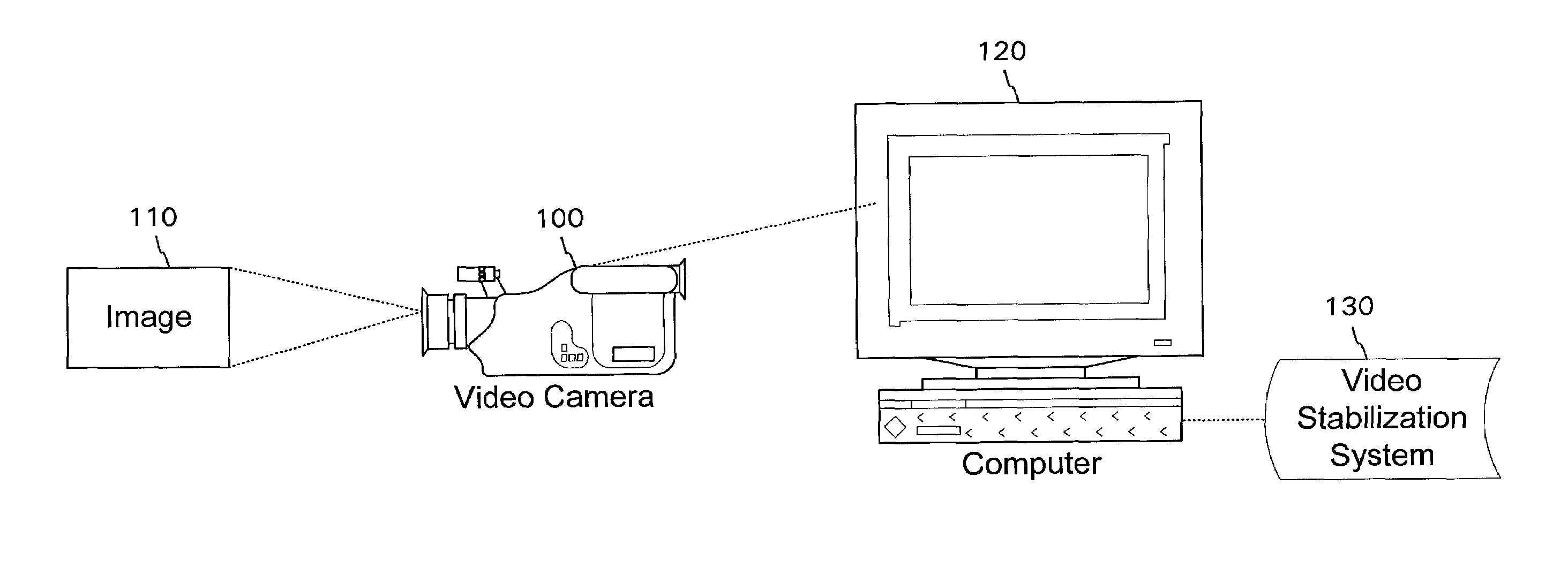
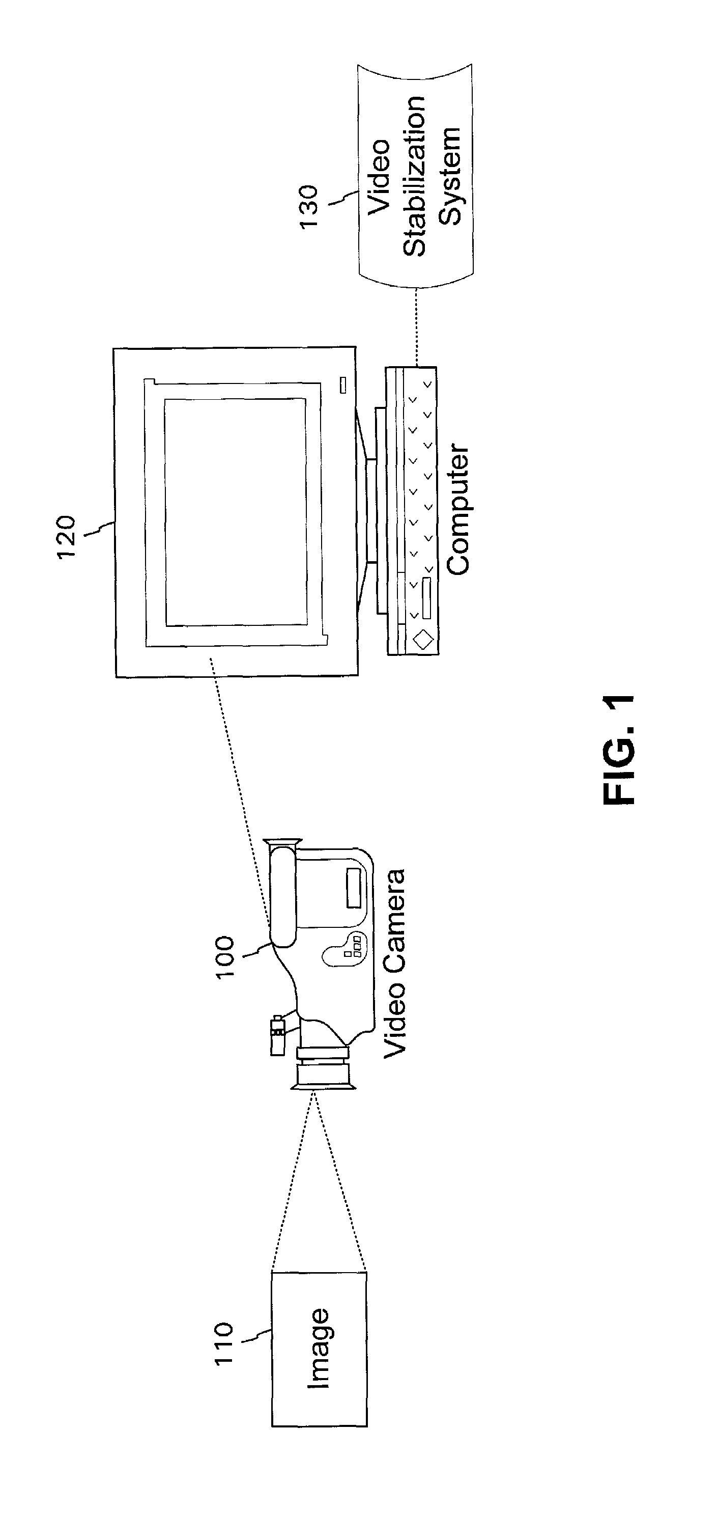
[0029]In accordance with an embodiment of the invention, a computer programmed with software (referred to herein as “video stabilization system”) processes a video segment to remove unwanted motion, resulting in a stabilized video segment. The video stabilization system tracks one or more features through multiple frames, identifies ideal positions for the features, and then generates transformation information (e.g., rotation, scaling, shearing, and / or translation) to transform all pixels in each frame to ideal positions based on the ideal positions of the features.

[0030]In particular, the video stabilization system of the invention tracks some features all the way through some video segment, rather than estimating camera motion between two frames. In one embodiment, a “feature” may be, for example, a point, line, region, edge, etc. For example, a feature may be a point of interest in an image that represents a large brightness change in two dimensions.

[0031]A video segment include...


PUM


Abstract

A video stabilization system processes a video segment to remove unwanted motion, resulting in a stabilized video segment. The video stabilization system tracks one or more features through multiple frames, identifies ideal positions for the features, and then generates information (e.g., rotation, scaling, shearing, and / or translation) to transform all pixels in each frame to ideal positions based on the ideal positions of the features.

Description

COPYRIGHT NOTICE[0001]A portion of the disclosure of this patent document contains material that is subject to copyright protection. The copyright owner has no objection to the facsimile reproduction by anyone of the patent document or the patent disclosure, as it appears in the Patent and Trademark Office patent files or records, but otherwise reserves all copyright rights whatsoever.BACKGROUND[0002]1. Field of the Invention[0003]The invention is generally related to digital image processing, and, in particular, is related to video stabilization.[0004]2. Description of Related Art.[0005]Video cameras are becoming more popular today as they become more widely available at lower prices. A video camera records sequential images within “frames.” A frame is a representation of an image at an instant of time. Each frame in a video segment (i.e., a sequence of frames) represents the image at a different instant in time. When several frames are recorded, at sequential instances in time, an...

Claims


Application Information

Patent Timeline
IPC IPC(8): G06K9/00H04N5/232
CPCH04N5/23248H04N5/23254H04N5/23264H04N23/6811H04N23/68H04N23/682
Inventor XIONG, WEI
Owner ARCSOFT
Learn More