Image forming apparatus

a technology of image forming and paper dust, applied in the field of image forming, can solve the problems of unintended color spots, difficulty in removing paper dust, and risk of undesirable formation of colored spots, etc., and achieve the effect of efficient removal of dus

Active Publication Date: 2007-05-22
BROTHER KOGYO KK
View PDF13 Cites 7 Cited by
  • Summary
  • Abstract
  • Description
  • Claims
  • Application Information

AI Technical Summary

Benefits of technology

[0010]The present invention was made in view of the problems discussed above. It is therefore an object of the present invention to provide a multiple-color image forming apparatus of a cleanerless type, which is arranged to efficiently remove a dust from image carriers.

Problems solved by technology

However, the apparatus still suffers from difficulty to remove paper dust which tends to adhere to the surface of the image carrier during a transfer of the toner image from the image carrier to the recording medium.
In the presence of the paper dust on the image carrier, the toner may adhere to the paper dust and may be transferred together with the paper dust to the recording medium, giving rise to a risk of undesirable formation of unintended colored spots (generally called “paper dust spots”) on the recording medium.
In the image forming apparatus of the cleanerless type, the paper dust cannot be removed from the image carrier, leading to the risk of formation of the paper dust spots on the recording medium.

Method used


Image

  • Image forming apparatus
  • Image forming apparatus
  • Image forming apparatus

Examples


first embodiment

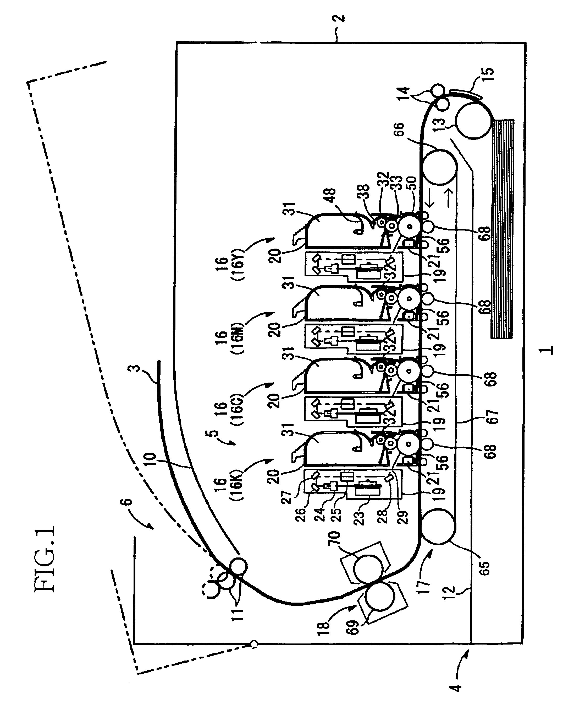
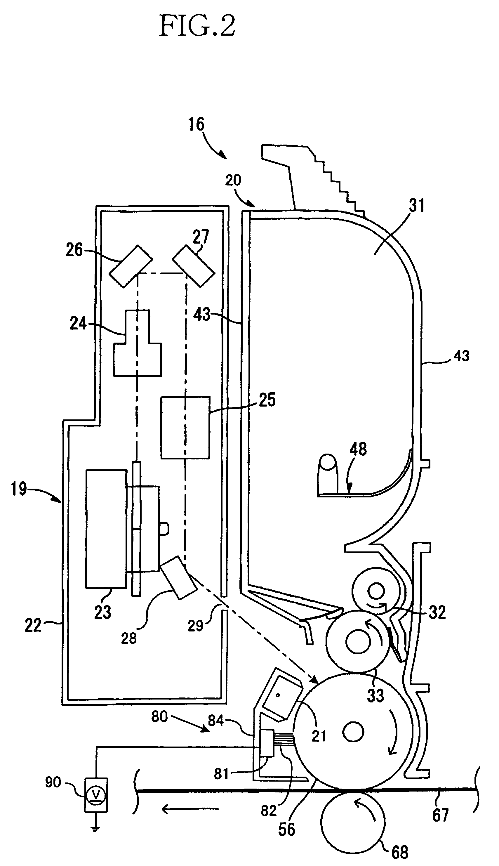
[0038]Referring first to FIGS. 1–3, a basic arrangement of a color laser printer 1 constructed according to the present invention will be described. As shown in FIG. 1, the present color laser printer 1 has a main body 2, which houses a paper supplying portion 4 arranged to supply a recording medium in the form of sheets of paper 3, an image forming portion 5 arranged to form a color image on the paper sheets 3 supplied from the paper supplying portion 4, and a paper ejecting portion 6 arranged to eject the paper sheets 3 on which the color image has been formed by the image forming portion 5. The image forming portion 5 includes four image forming units 16 which are arranged in tandem in the horizontal direction.

[0039]The paper supplying portion 4 includes a paper supply tray 12, a paper supply roller 13, and a pair of paper feed rollers 14. The paper supply tray 12 is removably installed in the bottom portion of the main body 2, such that the paper supply tray 12 can be inserted i...

second embodiment

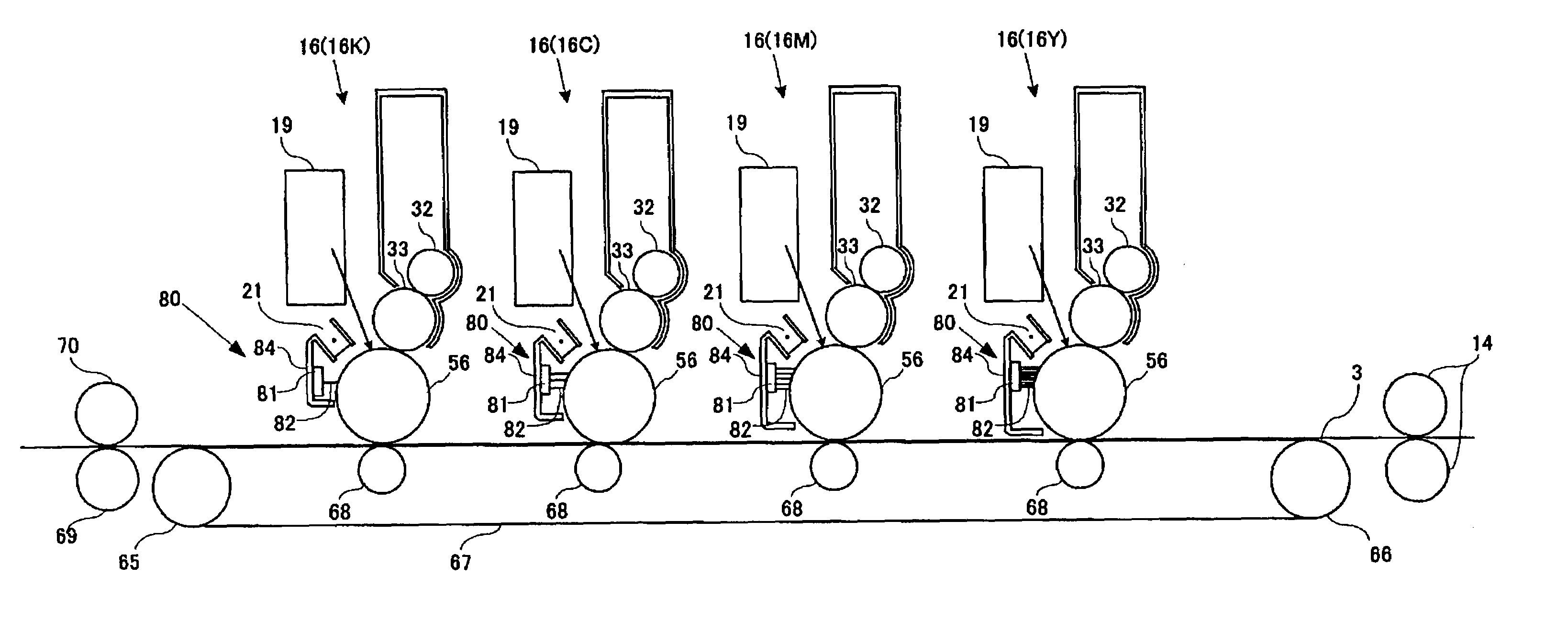
[0083]Referring next to FIG. 5, there will be described a color laser printer constructed according to the present invention, wherein the brushes of fibers 82 of the paper dust removing devices 80 of the four image forming units 16 have the same density, and the same dimension of contact with the photosensitive drums 56, but the bias voltage to be applied to the brushes of fibers 82 of the paper dust removing devices 80 of the image forming units 16 is reduced in the feeding direction of the paper sheet 3, to reduce the paper dust removing capacity of the paper dust removing devices 80, for increasing the service life of the photosensitive drums 56 of the relatively downstream image forming units 16M, 16C, 16K.

[0084]In the second embodiment described above, the amounts of removal of the paper dust from the photosensitive drums 56 of the relatively upstream image forming units 16Y, 16M are relatively large owing to the application of the relatively high bias voltage to the brushes of...

third embodiment

[0086]In the third embodiment, therefore, the paper dust is removed from the photosensitive drums 56 of the first three image forming units 16Y, 16M and 16C as counted from the most upstream unit 16Y, and the photosensitive drum 56 of the fourth or most downstream image forming unit 16K which is not provided with the paper dust removing device 80 is free from a contact pressure which would receive from the device 80 if provided for the unit 16K, so that the service life of the photosensitive drum 56 of the unit 16K can be increased.

[0087]The color laser printer according to the third embodiment of FIG. 6 is further advantageous in that the fourth image forming unit 16 which is not provided with the paper dust removing device 80 is the black image forming unit 16K which is generally operated most frequently and tends to have a comparatively short service life. In this respect, the elimination of the paper dust removing device 80 for this black image forming unit 16K results in an inc...


PUM


Abstract

An apparatus having image forming units to form respective toner images of different colors on a toner-image receiving medium, each unit including an image carrier, a static-latent-image forming portion to form a static latent image on the image carrier, a developing portion to apply a toner of the corresponding color to the image carrier, for forming the toner image on the image carrier, and a toner transferring portion to transfer the toner image from the image carrier to the medium, wherein the image forming units are disposed so as to be opposed to the medium and operable to sequentially transfer the toner images from the image carriers to the medium, and the developing portion of each unit is operable to adsorb the toner remaining on the image carrier after the toner image is transferred to the medium, and wherein at least the image forming unit located at the most upstream position of the apparatus is provided with a dust removing portion to remove, from the image carrier, a dust which has been transferred to the image carrier during a transfer of the toner image from the image carrier to the medium.

Description

[0001]The present application is based on Japanese Patent Application No. 2003-344654 filed on Oct. 2, 2003, the content of which is incorporated herein by reference.BACKGROUND OF THE INVENTION[0002]1. Field of the Invention[0003]The present invention relates in general to an image forming such as a color laser printer.[0004]2. Discussion of Related Art[0005]A conventional image forming apparatus such as a color laser printer is arranged to form a static latent image on a surface of an image carrier such as a photosensitive or photoconductive drum, and apply a toner to the surface of the image carrier, for thereby forming a toner image on the image carrier. This process is repeated for each of four toner images of different colors, which are formed on the respective image carriers, using respective yellow (Y), magenta (M), cyan (C) and black (K) toners, so that a color image is formed on a recording medium such as a sheet of paper, with the toner images of different colors being seq...

Claims


Application Information

Patent Timeline
Patent Type & Authority Patents(United States)
IPC IPC(8): G03G15/30G03G15/01G03G15/08G03G21/00G03G21/10
CPCG03G21/0064G03G2215/0119G03G2221/0042
Inventor NISHIMURA, SOICHIRO
Owner BROTHER KOGYO KK
Why Eureka
Try Eureka