Eureka AIR delivers breakthrough ideas for toughest innovation challenges, trusted by R&D personnel around the world.

Encased starting switch contact assembly protected against dust and small particles for a single-phase rotating electric machine and a method of assembling said switch

Inactive Publication Date: 2007-05-29
WEG INDUSTRIES
View PDF10 Cites 0 Cited by
  • Summary
  • Abstract
  • Description
  • Claims
  • Application Information

AI Technical Summary

Benefits of technology

[0019]The object of the present invention is to provide an encased starting switch contact assembly protected against dust and small particles for a single-phase rotating electric machine comprising: an auxiliary winding to start the machine until it reaches an operational speed; a mechanical starting switch consisting of a pair of blades made of a conducting material having highly conductive contacts at one of their ends, said blades movable between a first position where the contacts are in contact with each other to turn on the auxiliary winding and start the machine and a second position where the contact are apart from each other when the machine is running at an operational speed, thereby turning off said auxiliary winding; an actuating disk for moving said contacts between said first and second positions; a centrifugal actuator for driving said actuating disk; and a casing covering said contacts to protect against dust and small particles, wherein said casing comprises a substantially “L” shaped body defining a cylindrical main portion and a leg portion radially extending in a plane perpendicular to the axis of said main portion, said main portion having a first opening at its upped end and said leg having a second, elongated opening at its distal end.
[0020]Another object of the present invention is to provide an encased starting switch contact assembly as defined above, wherein the cylindrical main portion of said substantially “L” shaped body has a thin barreled wall to yield a minimum resistance to the movement of said contacts between said first and second positions.
[0022]A further object of the present invention is to provide an encased starting switch contact assembly as defined above wherein said casing is mounted on said contacts to protect them against dust and small particles.

Problems solved by technology

This is due to the fact that these switches usually operate in harsh environments, including some that may contain corrosive chemical substances and hazardous particles.
Also, some environments may have high humidity levels, and the combination of these contaminant elements may accelerate the deterioration of the active components of the starting switch, thereby jeopardizing its good operation and limiting its useful life.
Typically, a rotating electric machine is used to operate a saw or similar equipment and the chipped wood and dust resulting from the cutting process usually creates an environment that is very aggressive to the switch.
In yet another case, in an environment where cotton is manufactured, small particles of cotton in suspension in the air, when put in contact with the energized parts of the switch they may cause combustion due to the occurrence of sparks in the starting switch during its operation.
Another example of a harsh environment are the nautical applications, where the presence of salt spray penetrates into the parts of the electric machine, causing premature corrosion of the conductive parts.
Another concern is the presence of insects in some applications, which insects might as well enter the equipment and settle near the conducting parts of the contact, lately impairing its operation.
However, in addition to the problem of dissipating the heat generated by the machine in an encased construction, the increase in the manufacturing costs of such equipment is evident as more material is required to obtain the same power from the equipment due to the loss by heat.
If the auxiliary winding does not act together with the starting switch and the centrifugal actuator, this is an indication of engine failure and of the need of maintenance and cleaning of the set, which causes losses and drawbacks in the operation of the machine.

Method used


Image

  • Encased starting switch contact assembly protected against dust and small particles for a single-phase rotating electric machine and a method of assembling said switch
  • Encased starting switch contact assembly protected against dust and small particles for a single-phase rotating electric machine and a method of assembling said switch
  • Encased starting switch contact assembly protected against dust and small particles for a single-phase rotating electric machine and a method of assembling said switch

Examples


Embodiment Construction

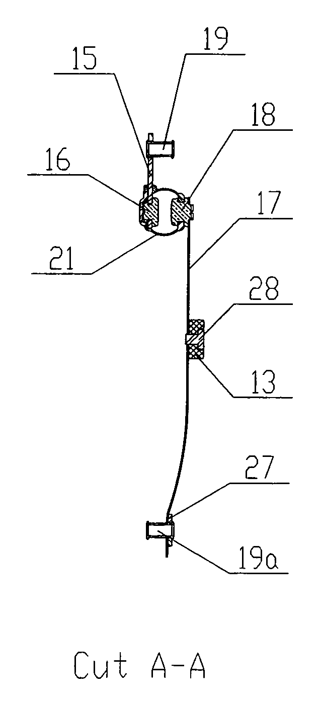
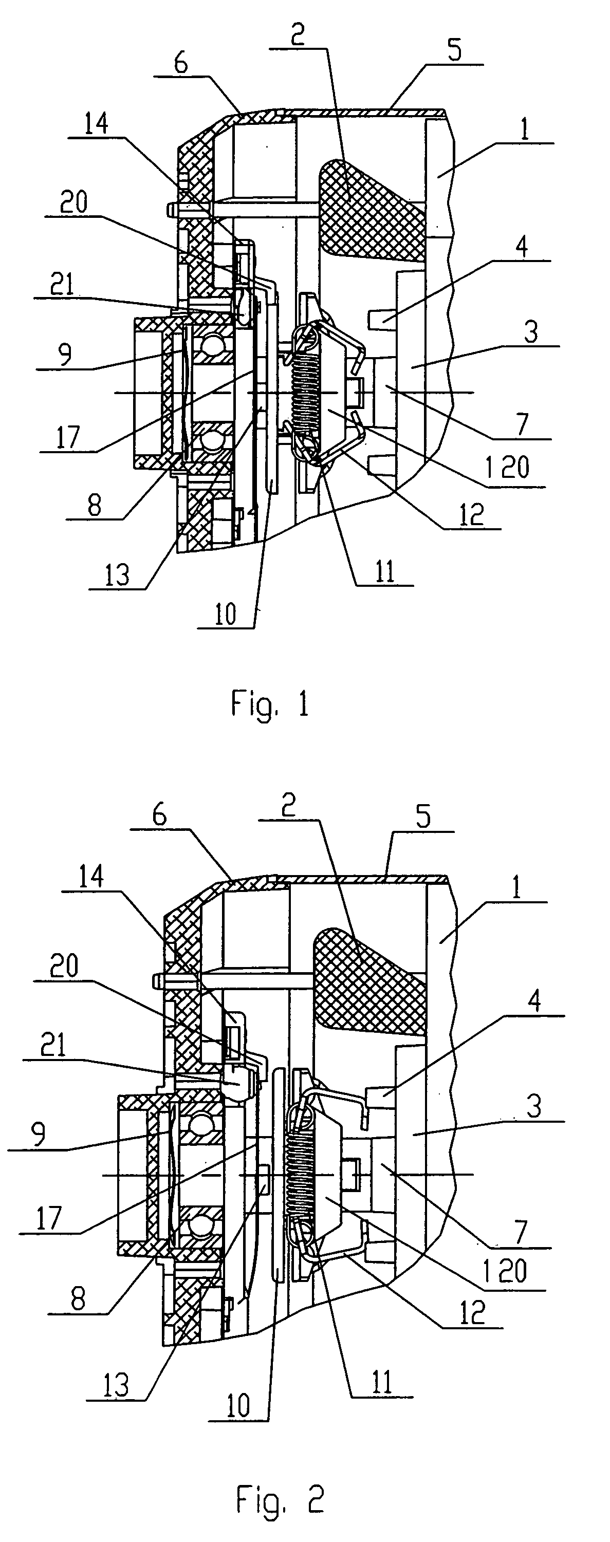
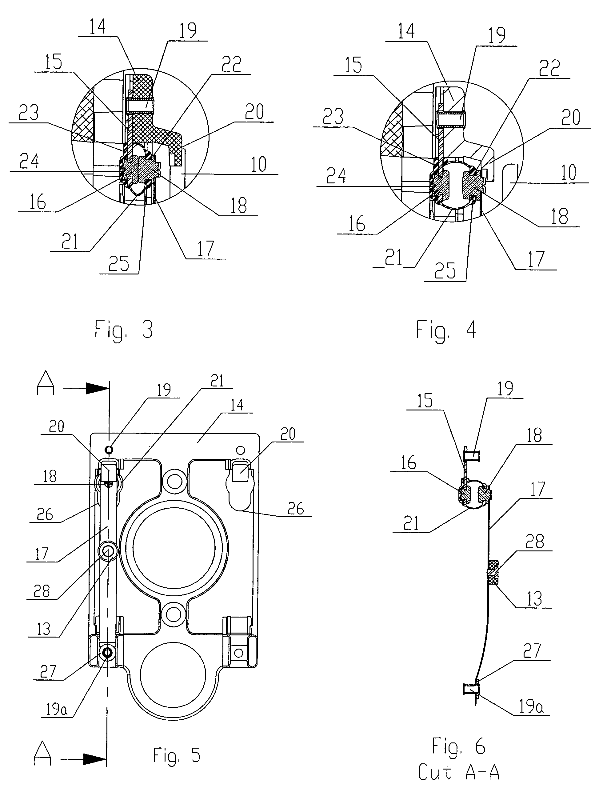
[0032]A specific embodiment presently preferred of the present invention is illustrated as an example in the accompanying drawings and will be described in details hereinafter. However, it should be understood that though the present invention is susceptible to several modifications and alterations in the form and dimensions, the purpose of the present specification is not to limit same to the particular forms and / or dimensions described herein but, instead, to cover all the modifications and alternative embodiments that are within the spirit and scope of the invention, as defined by the accompanying claims.

[0033]With reference now more particularly to the accompanying Figures, in which the same numerals have been used to indicate the same elements in the different views and, with particular reference to FIG. 1, an electric machine motor is shown in cross-sectional view in order to clarify its operation and the way the components involved in this process act.

[0034]The switch compris...


PUM


Abstract

The present invention refers to a starting switch having a protection against dust and small particles for rotating electric machines and to a method of assembling said switch. The switch according to the present invention provides an easy-to-assembly system for the several components that are part of the switch that does not require massive investments when compared to similar systems known to the state of the art while still providing an easy assembly due to the features of each component in the switch.

Description

CROSS-REFERENCE TO RELATED APPLICATION[0001]This application claims priority under 35 U.S.C. §119 of Brazilian patent application no. PI 0404224-0, filed Aug. 5, 2004, which is incorporated by reference herein.BACKGROUND OF THE INVENTION[0002]1. Field of the Invention[0003]The present invention refers to a starting switch having a protection against dust and small particles for rotating electric machines and to a method of assembling said switch.[0004]2. Description of the Related Art[0005]The protection of starting switches has been studied for years by the manufacturers of several types of rotating electric machines. This is due to the fact that these switches usually operate in harsh environments, including some that may contain corrosive chemical substances and hazardous particles. Also, some environments may have high humidity levels, and the combination of these contaminant elements may accelerate the deterioration of the active components of the starting switch, thereby jeopa...

Claims


Application Information

Patent Timeline
IPC IPC(8): H01H9/00H01H1/64H01H35/10
CPCH01H1/64H01H35/10
Inventor SILVA, MARCELO DE MELOSTOINSKI, VALMIR LUIS
Owner WEG INDUSTRIES
Why Eureka
Eureka Blog
Learn More