Broadband smart antenna and associated methods

a smart antenna and broadband technology, applied in the direction of elongated active element feed, resonant antenna, radiating element structure, etc., can solve the problems of increasing the cost increasing the antenna loss, and increasing the complexity of the design, so as to increase the bandwidth of a smart antenna and reduce the cost of the antenna. , the effect of increasing the bandwidth

Inactive Publication Date: 2007-05-29
INTERDIGITAL TECH CORP
View PDF12 Cites 21 Cited by
  • Summary
  • Abstract
  • Description
  • Claims
  • Application Information

AI Technical Summary

Benefits of technology

[0007]In view of the foregoing background, it is therefore an object of the present invention to increase the bandwidth of a smart antenna with minimum increases in antenna loss and costs.
[0010]The different size passive antenna elements are thus stagger-tuned passive antenna elements, which creates a series of different resonant frequencies for increasing a bandwidth of the smart antenna. A wider bandwidth is advantageously achieved while minimizing additional antenna loss and production costs.

Problems solved by technology

A wider bandwidth often requires a more complex design, which could increase antenna loss.
Alternatively, reactive components can be added to increase the bandwidth, but this adds to the cost of a smart antenna.

Method used


Image

  • Broadband smart antenna and associated methods
  • Broadband smart antenna and associated methods
  • Broadband smart antenna and associated methods

Examples


Embodiment Construction

[0028]The present invention will now be described more fully hereinafter with reference to the accompanying drawings, in which preferred embodiments of the invention are shown. This invention may, however, be embodied in many different forms and should not be construed as limited to the embodiments set forth herein. Rather, these embodiments are provided so that this disclosure will be thorough and complete, and will fully convey the scope of the invention to those skilled in the art. Like numbers refer to like elements throughout, and prime and double prime notations are used to indicate similar elements in alternative embodiments.

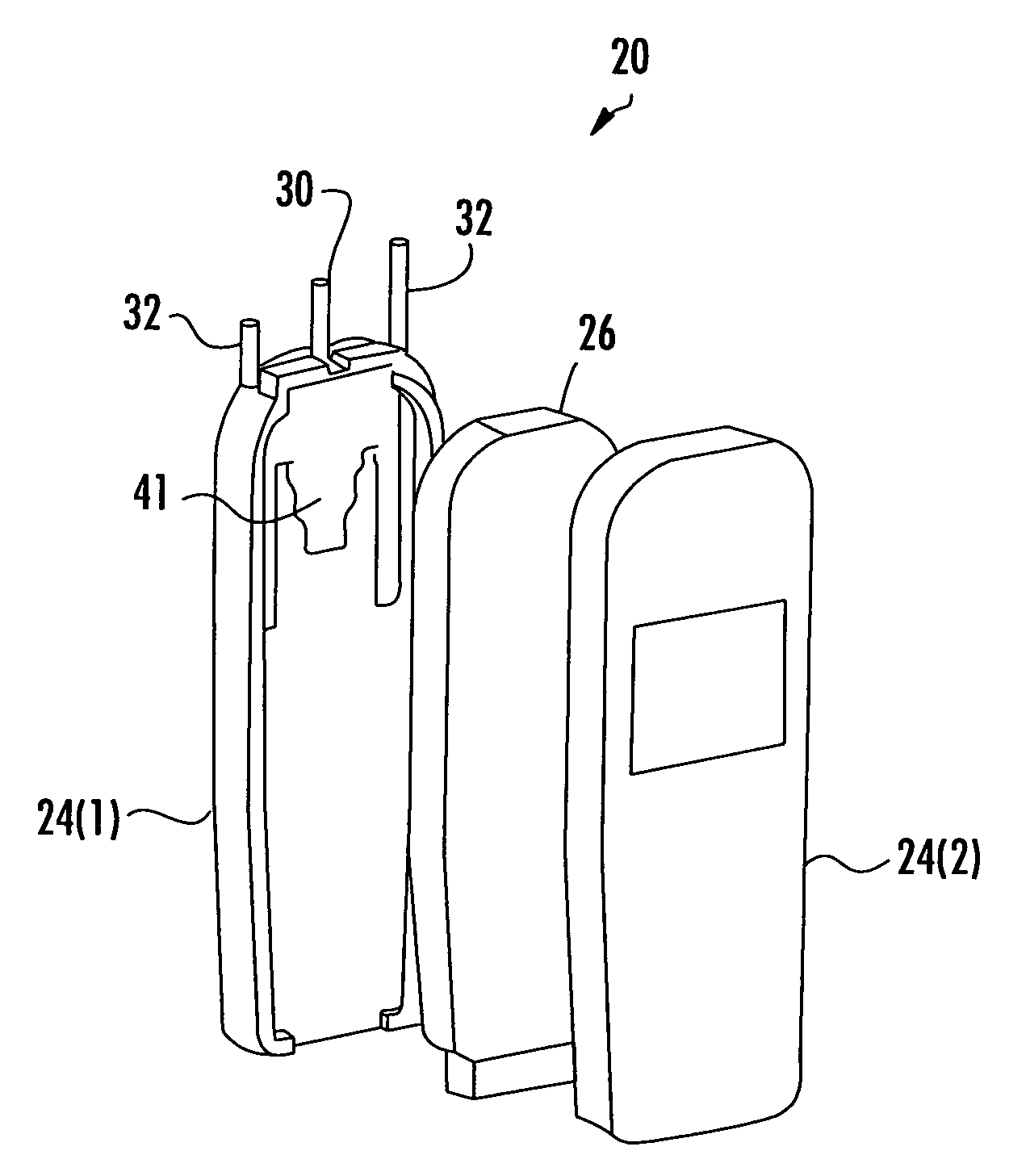
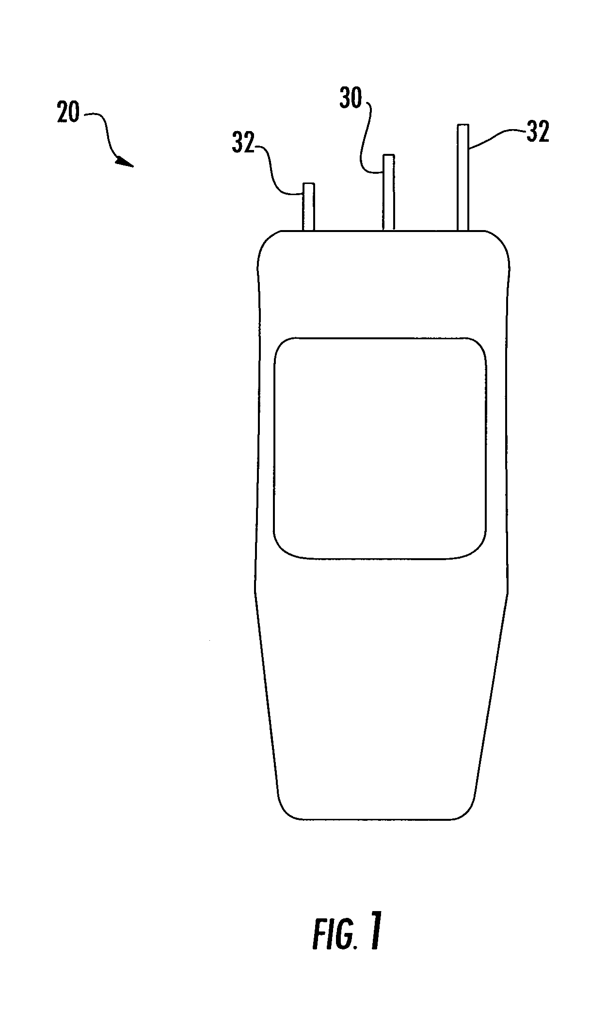
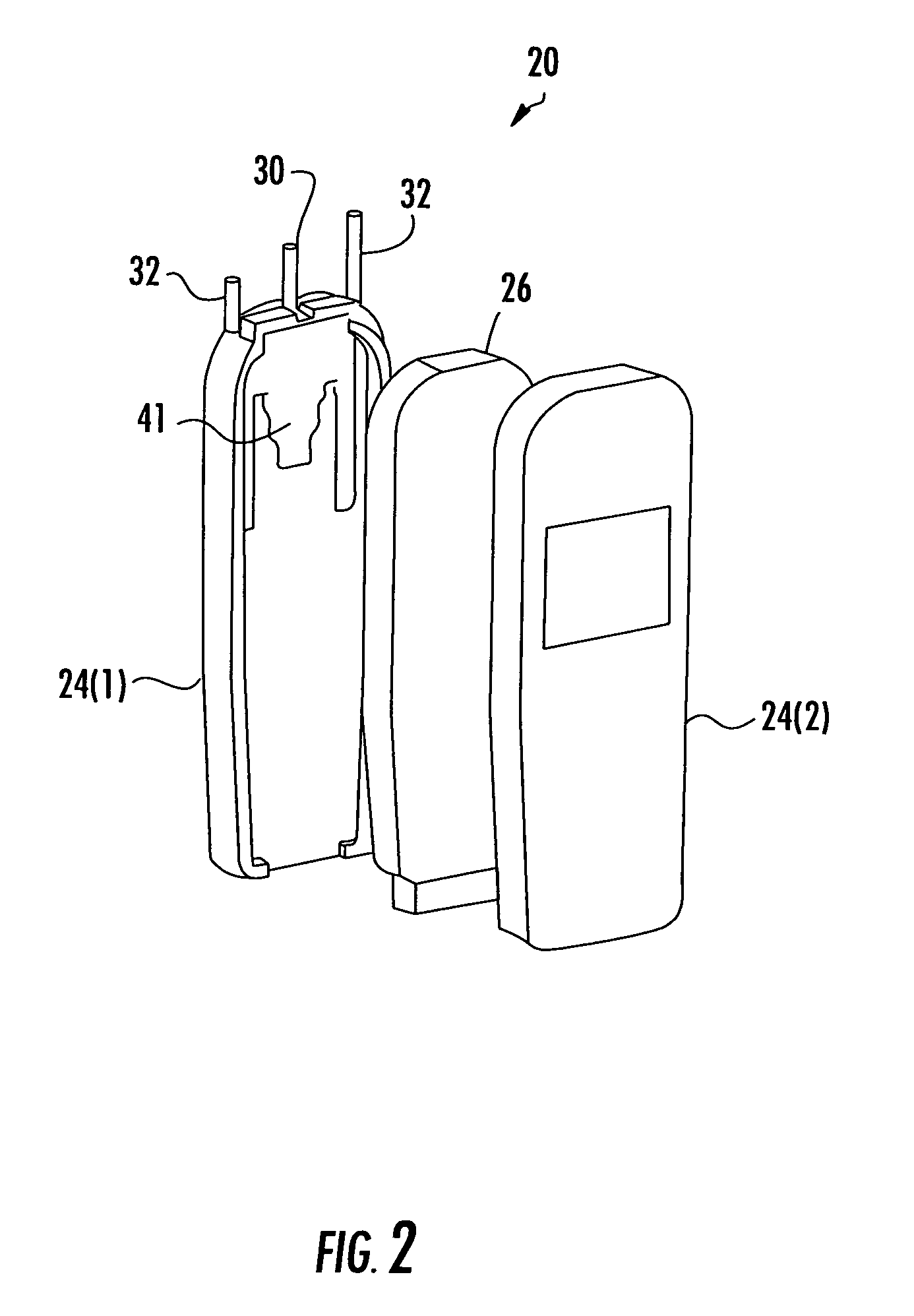
[0029]Referring initially to FIGS. 1–4, the illustrated mobile subscriber unit 20 includes in FIGS. 1 and 2 a smart antenna 22 that protrudes from the housing 24 of the mobile subscriber unit 20, and in FIGS. 3 and 4 a smart antenna that is internal the housing 24. In both cases, the smart antenna 22 includes an active antenna element 30 and a plurality o...


PUM


Abstract

A smart antenna includes a ground plane, an active antenna element adjacent the ground plane, and passive antenna elements adjacent the ground plane. The passive antenna elements have different sizes for defining different resonant frequencies for increasing a bandwidth of the smart antenna. Dielectric layers having different dielectric constants may also be used for coating the passive antenna elements for defining different resonant frequencies. Impedance elements are connected to the ground plane and are selectively connectable to the passive antenna elements for antenna beam steering.

Description

RELATED APPLICATION[0001]This application claims the benefit of U.S. Provisional Application Ser. No. 60 / 592,084 filed Jul. 29, 2004, the entire contents of which are incorporated herein by reference.FIELD OF THE INVENTION[0002]The present invention relates to the field of wireless communication systems, and more particularly, to a broadband smart antenna.BACKGROUND OF THE INVENTION[0003]In wireless communication systems, portable or mobile subscriber units communicate with a centrally located base station within a cell. The wireless communication systems may be a CDMA2000, GSM and WLAN communication system, for example. The subscriber units are provided with wireless data and / or voice services and can connect devices such as, for example, laptop computers, personal digital assistants (PDAs), cellular telephones or the like through the base station to a network.[0004]Each subscriber unit is equipped with an antenna. To increase the communications range between the base station and t...

Claims


Application Information

Patent Timeline
Patent Type & Authority Patents(United States)
IPC IPC(8): H01Q19/00
CPCH01Q1/242H01Q1/243H01Q1/38H01Q5/385H01Q9/32H01Q19/22H01Q3/446
Inventor CHIANG, BING A.LYNCH, MICHAEL J.RICHESON, LEGAL REPRESENTATIVE, DEE M.WOOD, DOUGLAS H.RICHESON, DECEASED, JOSEPH T.
Owner INTERDIGITAL TECH CORP
Why Eureka
Try Eureka