
Eureka
For R&D, Eureka makes reading and utilizing patents & technical documents easy.
Eureka AIR
Designed for self-driven R&D workflows. Generate viable solutions, solve complex R&D challenges, empower your innovation with AI.

Eureka Materials
Designed for material experts only. Revolutionize your material R&D, from search, analyze, to developing new materials.

TechResearch
Generate reliable direction feasibility study reports for your R&D in just a few steps.

TechSeek
Discover and master advanced knowledge NOW. Basics, ideas, possibilities, all at once.

TechMind
As an expert in R&D Theories, TechMind can generates customized viable solutions instantly.

TechRisk
Analyze your overall solution with one click, know your potential R&D risks in advance.

TechMonitor
Get weekly tech updates, stay abreast of the latest tech innovations and key insights.
DMD-based image display systems
- Summary
- Abstract
- Description
- Claims
- Application Information
AI Technical Summary
Benefits of technology
Problems solved by technology
Method used
Image

Examples
Embodiment Construction
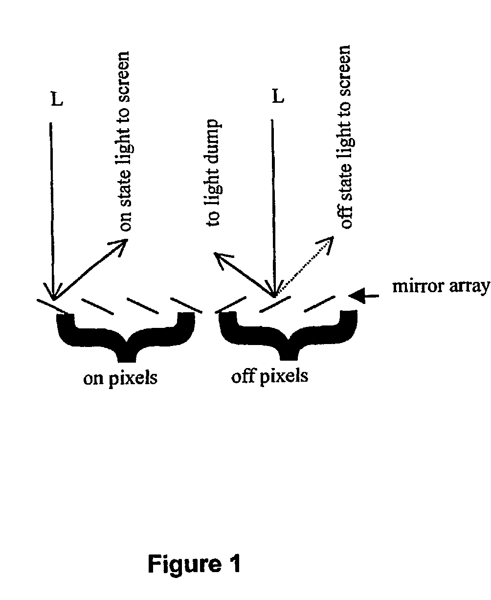
[0035]For SLMs such as DMDs where mechanical switching is used, the maximum number of bits possible with a binary PWM scheme is determined by the period of the LSB. For current DMD devices the minimum period of the LSB is equal to the mechanical switching time of the mirrors, which is about 20 μsec. For a frame rate of 24 fps, the period of the LSB means that a total of 11 bits can be represented in the 41.67 msec. available for each frame. The number of possible bits determines the total number of steps available to represent a grayscale image, and this corresponds to the dynamic range of the resulting image.
[0036]It should also be clear that increasing the frame rate reduces the time available for the creation of various bit durations using binary PWM, and as a result the number of bits available is reduced, as is the corresponding dynamic range.
[0037]The contrast ratio of a system is limited by the maximum difference between the dark level of the SLM and the maximum light level t...
PUM
 Abstract
Description
Claims
Application Information
 - R&D Engineer
- R&D Manager
- IP Professional
- Industry Leading Data Capabilities
- Powerful AI technology
- Patent DNA Extraction
Browse by: Latest US Patents, China's latest patents, Technical Efficacy Thesaurus, Application Domain, Technology Topic, Popular Technical Reports.
© 2024 PatSnap. All rights reserved.Legal|Privacy policy|Modern Slavery Act Transparency Statement|Sitemap|About US| Contact US: help@patsnap.com