Production method of stacked piezoelectric element

a piezoelectric element and production method technology, applied in piezoelectric/electrostrictive transducers, generators/motors, variable capacitors, etc., can solve the problems of silver and insulation failure migration, inability to manufacture in mass quantities, and inability to achieve mass production, so as to improve the durability of the stacked piezoelectric element, the effect of easy formation

Inactive Publication Date: 2007-06-05
DENSO CORP
View PDF11 Cites 17 Cited by
  • Summary
  • Abstract
  • Description
  • Claims
  • Application Information

AI Technical Summary

Benefits of technology

[0019]By virtue of such a structure, in the case of applying coating or the like of an insulating resin material so as to ensure insulation of the inner electrode layer of the stacked piezoelectric element, the insulating resin material intruded into the groove part exerts a so-called anchor effect and the coating state can be more stable than in conventional techniques, whereby the stacked piezoelectric element obtained can be enhanced in durability.
[0020]Furthermore, in providing many groove parts on the side face of the stacked piezoelectric element, this can be attained, as described above, by only forming a unit body having a specific structure and stacking the unit bodies, and a specific machining operation conventionally required for forming groove parts, such as cutting work by a cutting saw, is not necessary, so that the groove part can be very easily formed and at the same time, the stacked piezoelectric element (stacked body) can be free from damaging at the formation of groove parts.
[0021]In this way, according to the present invention, a method for producing a stacked piezoelectric element, where groove parts can be easily formed on the side face of a stacked body without causing damages, can be provided.

Problems solved by technology

However, a stacked piezoelectric element having excellent durability and applicable to the actuator of those injectors has not yet been put into practice at present.
However, this method has a problem in that if the resin coat is stripped off, water or the like intrudes to cause migration of silver and insulation failures.
However, it is not practicable, in mass production, to machine grooves having a depth of 500 μm and a height (width) of 50 μm by a cutting saw as disclosed in this patent document.
However, machining of grooves by a cutting saw is industrially difficult in view of the working efficiency and, also, the stacked body may be damaged during the machining to cause a problem in quality.

Method used


Image

  • Production method of stacked piezoelectric element
  • Production method of stacked piezoelectric element
  • Production method of stacked piezoelectric element

Examples


examples

[0063]The method for producing a stacked piezoelectric element of the present invention is described below by referring to FIGS. 1 to 11.

[0064]As shown in FIGS. 5 and 6, the stacked piezoelectric element 1 produced in this Example is a stacked piezoelectric element obtained by alternately stacking a piezoelectric layer 11 comprising a piezoelectric material and an inner electrode layer 2 comprising an electrically conducting material.

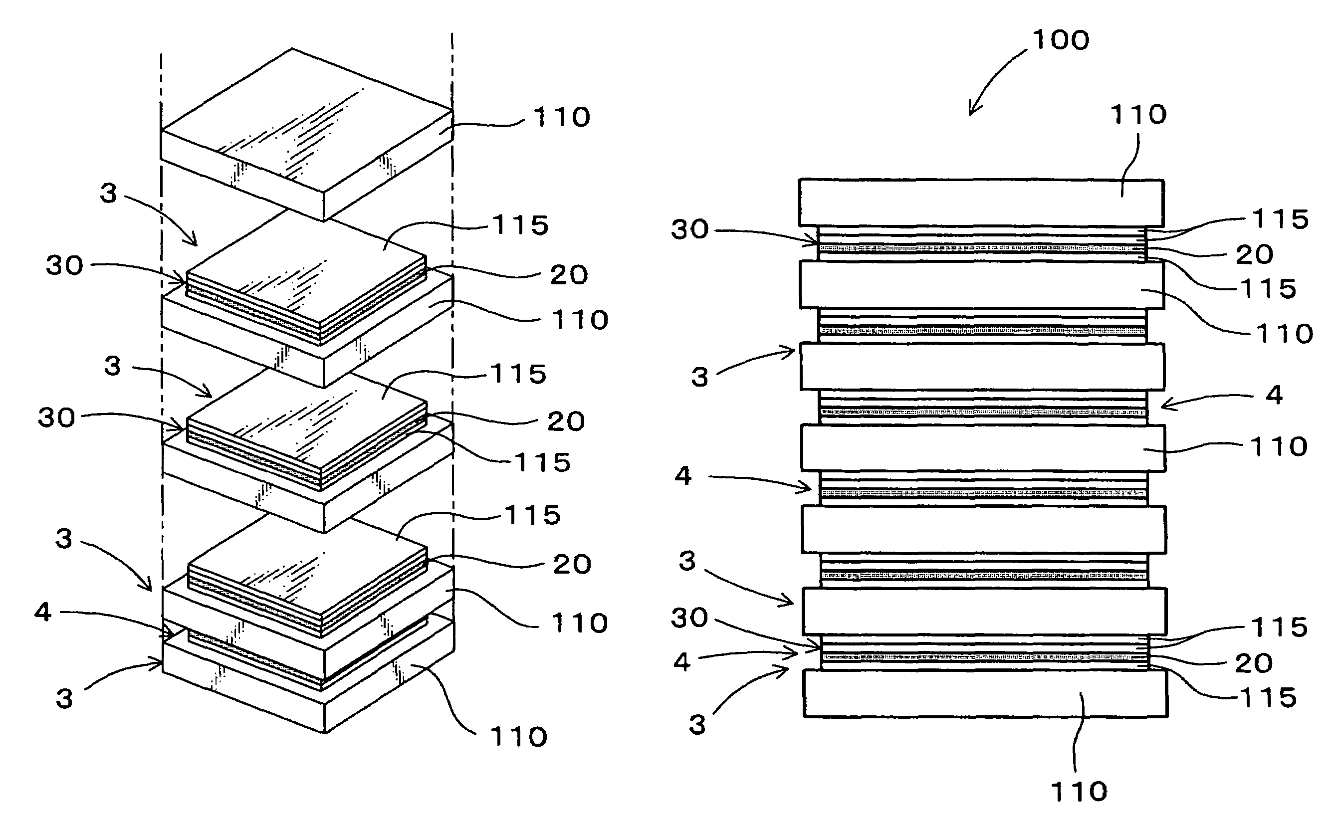
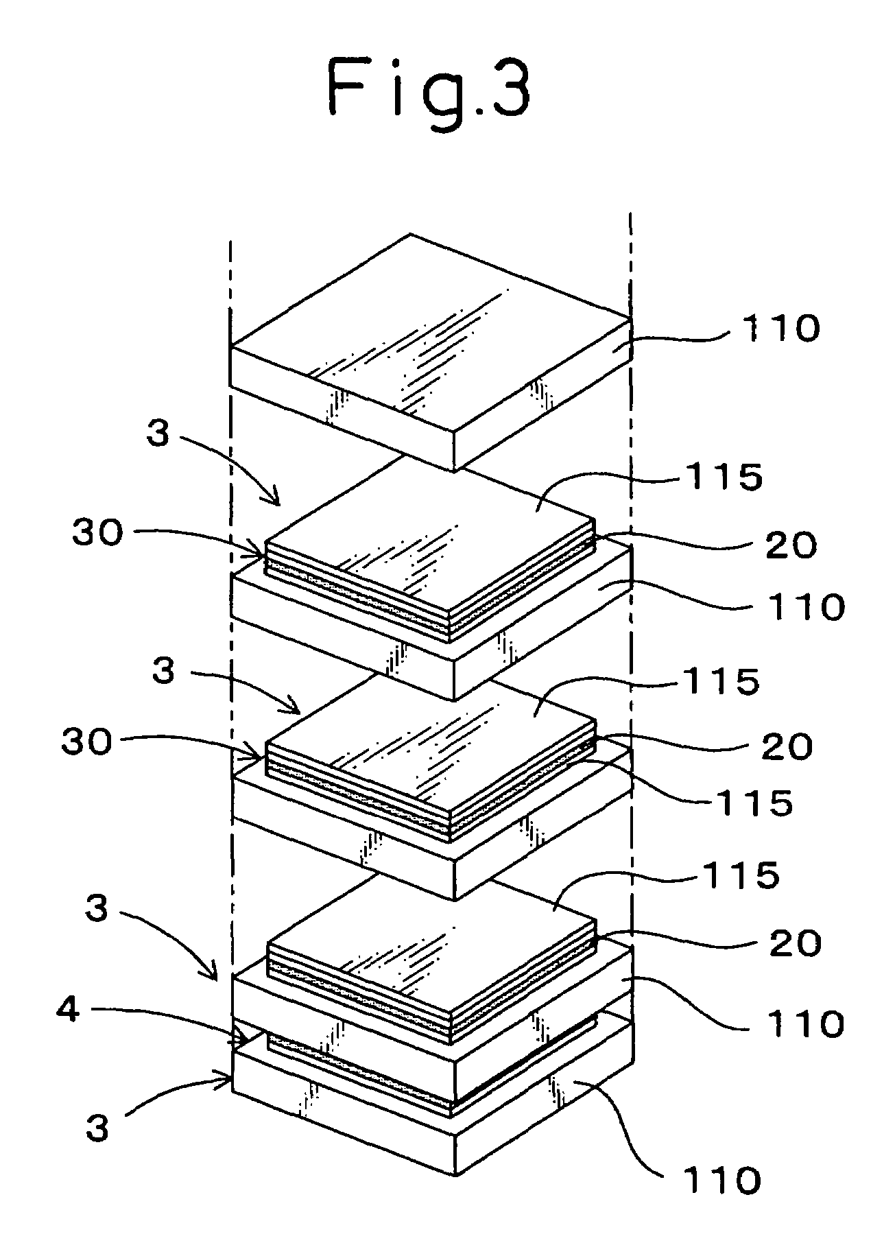
[0065]In producing this stacked piezoelectric element 1, as shown in FIGS. 1 to 6, at least a green sheet production step, a unit body formation step, a stacked body formation step and a firing step, which are described below, are performed.

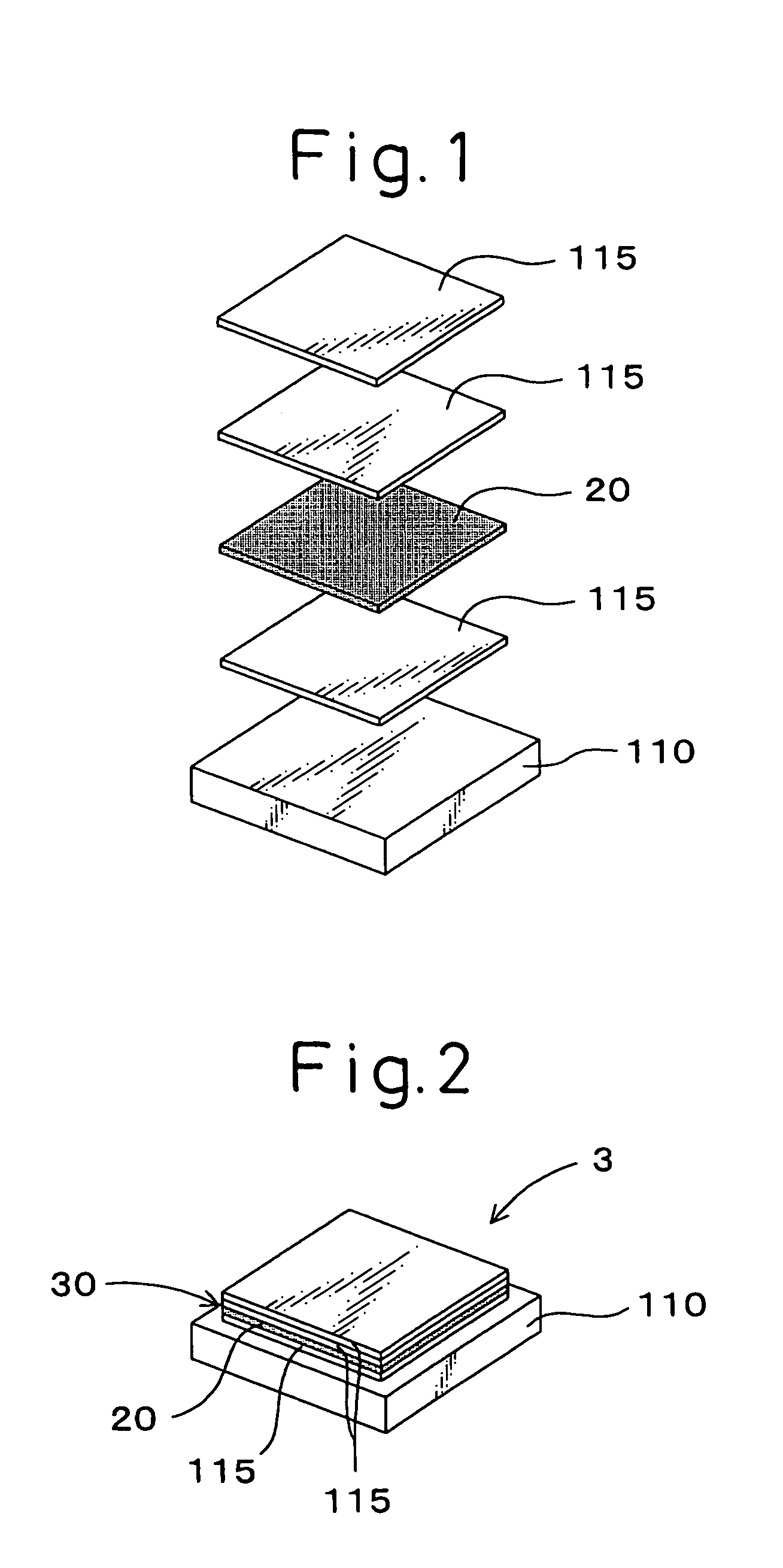
[0066]The green sheet production step is a step of producing a green sheet 110 for base (FIG. 1), which constitutes a part of the piezoelectric layer 11.

[0067]The unit body formation step is, as shown in FIGS. 1 and 2, a step of forming a unit body 3 by disposing a narrow stacked part 30 on the green sheet 110 for ba...

example 2

[0086]In this Example, as shown in FIGS. 12 to 15, the shape of the inner electrode layer 2 exposed to the groove part 4 of the stacked piezoelectric element 1 is alternately changed.

[0087]More specifically, in the unit body formation step of this Example, as shown in FIG. 12, the narrow stacked part 30 is formed such that the electrode material layer 20 comes into direct contact with the green sheet 110 for base. Then, a takeout electrode part 22 is formed in the electrode material layer 20 by extending a part (one side part 201) of the outer periphery of the electrode material layer to the position nearly flush with the outer peripheral end face 111 of the green sheet 110 for base constituting the unit body 3.

[0088]In the stacked body formation step, a stacked body 100 is obtained, as shown in FIG. 13, by stacking the unit bodies 3 such that the takeout electrode parts 22 appear alternately on the right and left.

[0089]Thereafter, the firing step is performed in the same manner as ...

example 3

[0093]In the unit body formation step of this Example, as shown in FIG. 16, a unit body 3 is formed by disposing a plurality of narrow stacked parts 30 on one wide sheet-like green sheet for a base while leaving a gap between respective narrow stacked parts and cutting and separating the green sheet 110 for base along the gaps.

[0094]More specifically, as shown in the Figure, a narrow piezoelectric material layer 115 and an electrode material 20 are disposed on one wide sheet-like green sheet 110 for base by printing in the same manner as in Example 1 to form a plurality of narrow stacked parts 30.

[0095]Thereafter, the green sheet 110 for base is cut and separated along the cutting line (broken line C), whereby a plurality of unit bodies 3 (FIG. 2) can be obtained from one green sheet 110 for base.

[0096]In this case, the production of unit body 3 can be more efficiently performed. In addition, the same operational effects as in Example 1 can be obtained.


PUM

PropertyMeasurementUnit
thicknessaaaaaaaaaa
thicknessaaaaaaaaaa
widthaaaaaaaaaa

Abstract

A stacked piezoelectric element is produced by alternately stacking a piezoelectric layer and an inner electrode layer. The method includes producing a green sheet 110 for a base, forming a unit body 3 having a narrow stacked part 30 where a narrow piezoelectric material layer 115 having an area smaller than the green sheet 110 for base and an electrode material layer 20 having an area smaller than the green sheet 110 for base are stacked, the unit body being formed by disposing the narrow stacked part 30 on the green sheet 110 for base; forming a stacked body having groove parts by stacking a plurality of the unit bodies 3, the groove part having the bottom being defined by the side face of the narrow stacked part 30; and firing the stacked body.

Description

[0001]This application claims priority to application Ser. No. 2003-157116, filed 02 Jun. 2003. The entire contents of this application is incorporated herein by reference.FIELD OF THE INVENTION[0002]The present invention relates to a method for producing a stacked piezoelectric element by alternately stacking a piezoelectric layer and an inner electrode layer.BACKGROUND OF THE INVENTION[0003]Recently, in view of improving the fuel consumption and cleaning the exhaust gas of automobiles, development of injectors capable of more precisely controlling the fuel injection is demanded. As for such a highly precise injector, use of a stacked piezoelectric element as the actuator has been proposed. However, a stacked piezoelectric element having excellent durability and applicable to the actuator of those injectors has not yet been put into practice at present.[0004]The stacked piezoelectric element can be produced, for example, by printing and forming an inner electrode layer of 5 μm on a...

Claims


Application Information

Patent Timeline
Patent Type & Authority Patents(United States)
IPC IPC(8): H04R17/00H01L41/22H01L41/083H01L41/187H01L41/27H01L41/297
CPCH01L41/083H01L41/273Y10T29/49126Y10T29/435Y10T29/49155Y10T29/42H10N30/50H10N30/053
Inventor IWASE, AKIOITOU, TETSUJIOOSHIMA, TOSHIOKADOTANI, SHIGE
Owner DENSO CORP
Why Eureka
Try Eureka