
Steel joining tool

Inactive Publication Date: 2007-06-05
HICKS LARRY TRUETT
View PDF6 Cites 4 Cited by
  • Summary
  • Abstract
  • Description
  • Claims
  • Application Information

AI Technical Summary

Benefits of technology

[0008]Accordingly, several objects and advantages of the described invention are:
[0009](a) to provide a tool that is safe;
[0010](b) to provide a tool that is easy to use;
[0011]

Problems solved by technology

Warehouse employees for many years have had the unpleasant job of changing the horizontal beams that are used for storage of merchandise, to raise or lower height.
Sometimes if they are very tight a fork lift is used resulting in damage to beams, noise and injury.
After steel is loaded with pallets it is in more of a strain or bind making the process more difficult.

Method used


Image

  • Steel joining tool
  • Steel joining tool
  • Steel joining tool

Examples


Embodiment Construction

—PREFERRED EMBODIMENT

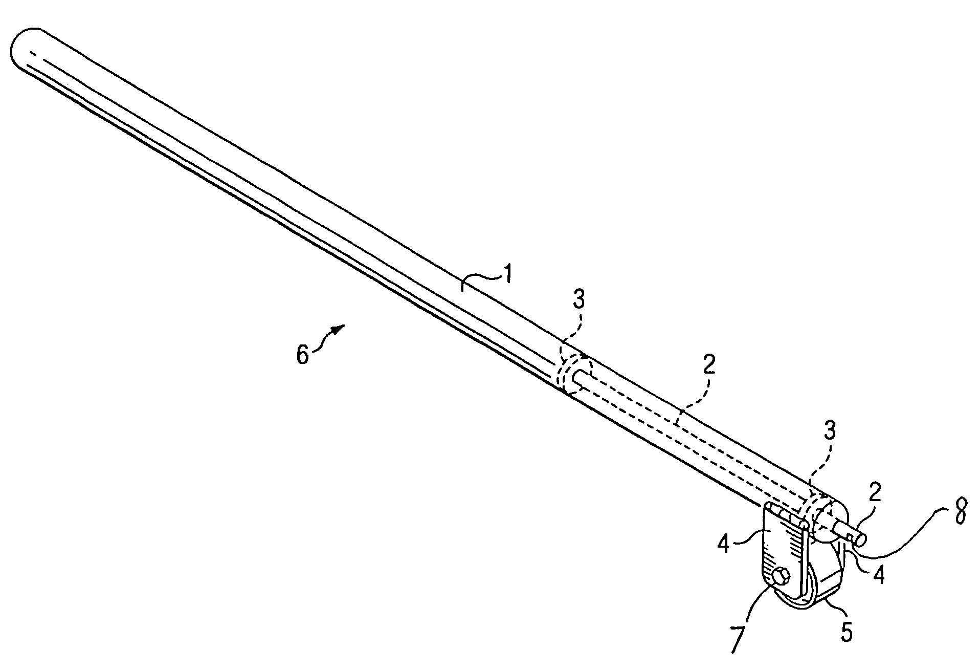
[0017]An elongated body having a first end and a second end with tip extending from front end. One or more legs to support one or more wheels at front end close to tip. Body is steel 2.54 cm (1 inch), inside diameter pipe approximately 71.12 cm (28 inches) long. Legs are steel 3.81 cm by 6.35 cm (1½ by 2½ inches) are welded to body to support wheel approximately 2.54 cm (1 inch) behind where tip is connected to body. All measurements are approximate.

[0018]This description should not be constructed as limitations on the scope of invention but be considered my preferred embodiment. There are other variations for example folding leg, larger wheel, wider wheel, and adjustable supports.

DESCRIPTION OF DRAWINGS

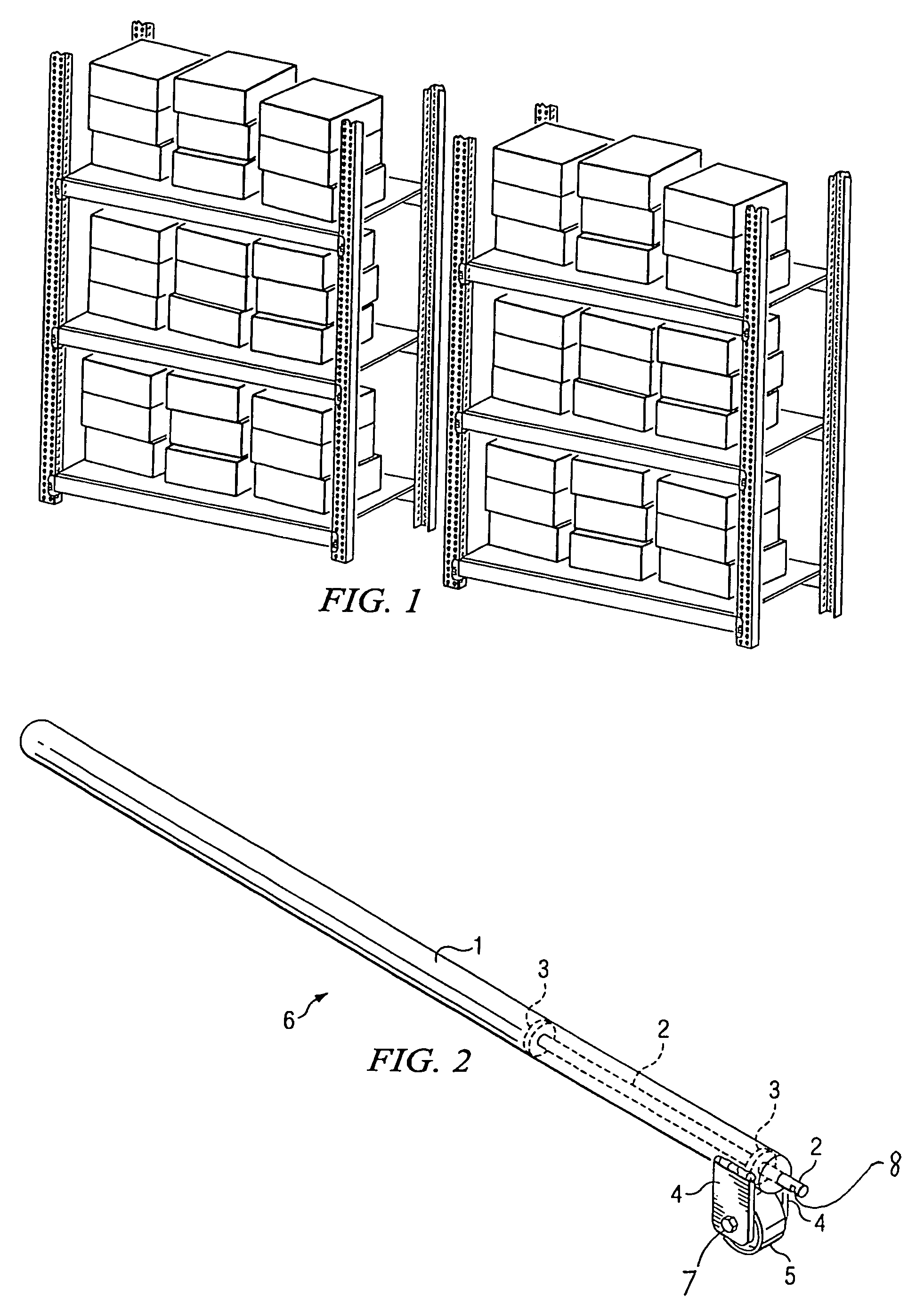
[0019]FIG. 1 shows view of steel shelf units used in industrial and retail warehouses.

[0020]FIG. 2 shows view of completed tool.[0021]1 elongated body or handle[0022]2 steel core element[0023]3 washers[0024]4 leg supports[0025]5 wheel[0026]7 bolt[0027]8 V-cut

[002...


PUM

PropertyMeasurementUnit
Angleaaaaaaaaaa
Perimeteraaaaaaaaaa

Abstract

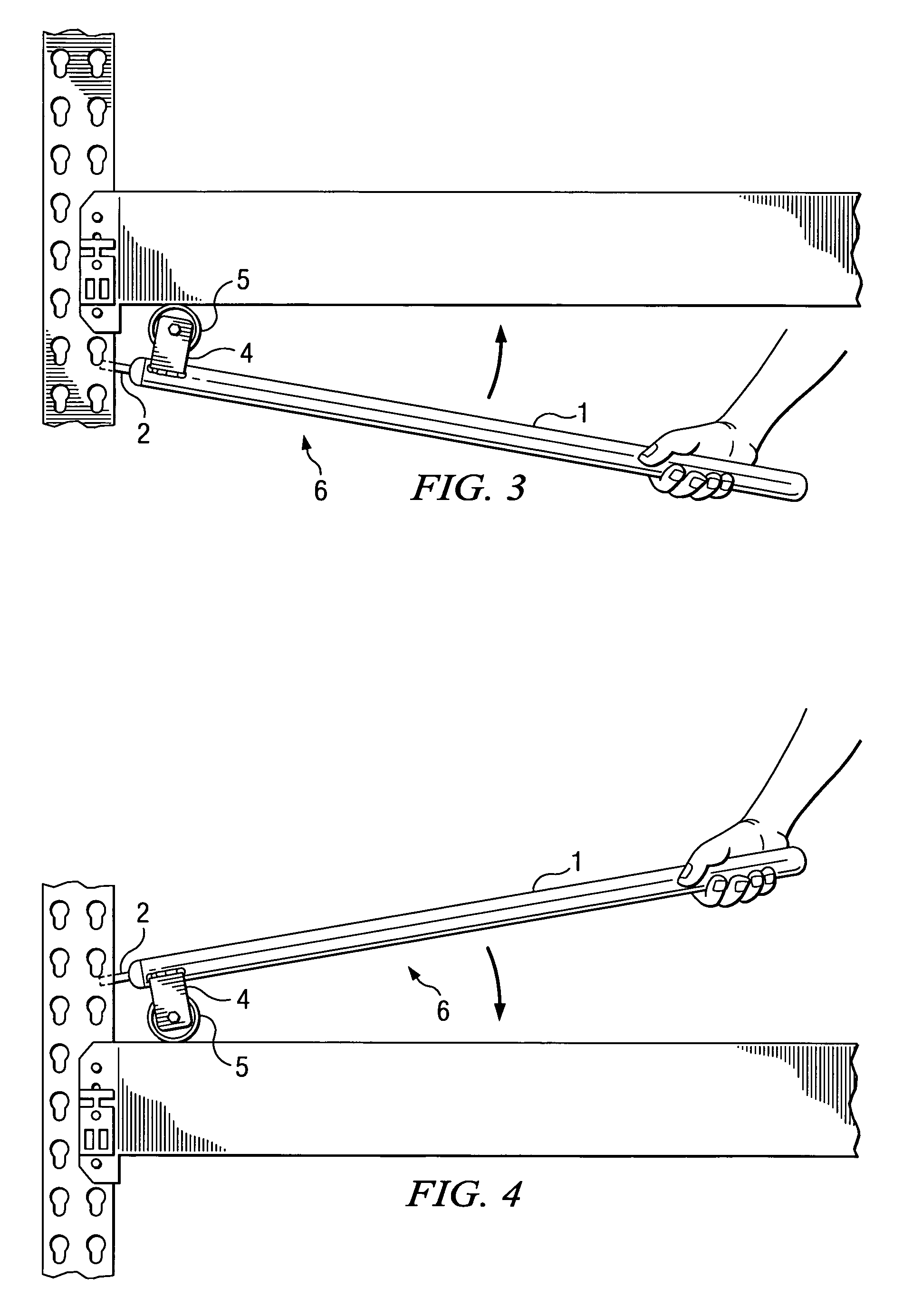
A new tool that connects horizontal bar to vertical bar and disconnects same. V-shaped cut or slots in tip locks in vertical bar opening at a desired angle. Wheel sets on horizontal bar and pushes down to lock into vertical bar. Set tool upside down on bottom of horizontal bar and lift to raise or disconnect horizontal bar from vertical bar.

Description

CROSS-REFERENCE TO RELATED APPLICATIONS[0001]This application claims the benefit of provisional patent application Ser. No. 60-543,349, filed 2004 Feb. 10 by the present inventor. Disclosure document filed 2003 Dec. 18.FEDERALLY SPONSORED RESEARCH[0002]Not ApplicableSEQUENCE LISTING OR PROGRAM[0003]Not ApplicableBACKGROUND OF THE INVENTION[0004]1. Field of Invention[0005]This invention relates generally to the field of manufacturing and process, specifically to steel shelving as used in storage facilities.[0006]2. Prior Art[0007]Warehouse employees for many years have had the unpleasant job of changing the horizontal beams that are used for storage of merchandise, to raise or lower height. The most used method is a sledge hammer or dead weight. Sometimes if they are very tight a fork lift is used resulting in damage to beams, noise and injury. After steel is loaded with pallets it is in more of a strain or bind making the process more difficult.OBJECTS AND ADVANTAGES[0008]Accordingl...

Claims


Application Information

Patent Timeline
IPC IPC(8): B23P19/04
CPCB25B27/00B66F15/00Y10T29/53896Y10T29/53943
Inventor HICKS, LARRY TRUETT
Owner HICKS LARRY TRUETT
Learn More