Trapped vortex cavity afterburner

a vortex cavity and afterburner technology, applied in the ignition of turbine/propulsion engines, engine starters, lighting and heating apparatus, etc., can solve the problems of loss of performance and general heavyness of the afterburner

Active Publication Date: 2007-06-05
GENERAL ELECTRIC CO
View PDF6 Cites 105 Cited by
  • Summary
  • Abstract
  • Description
  • Claims
  • Application Information

AI Technical Summary

Problems solved by technology

Augmentors are generally heavy, include many parts such as the flameholders and fuel injectors, and are inefficient if used as a partial reheat situation such in engines that operate at subsonic flight speeds only even when operating wet.
The flameholders and spraybars extend into the nozzle's flowpath thus causing a loss of performance particularly during dry operation of the engine.

Method used


Image

  • Trapped vortex cavity afterburner
  • Trapped vortex cavity afterburner
  • Trapped vortex cavity afterburner

Examples


Embodiment Construction

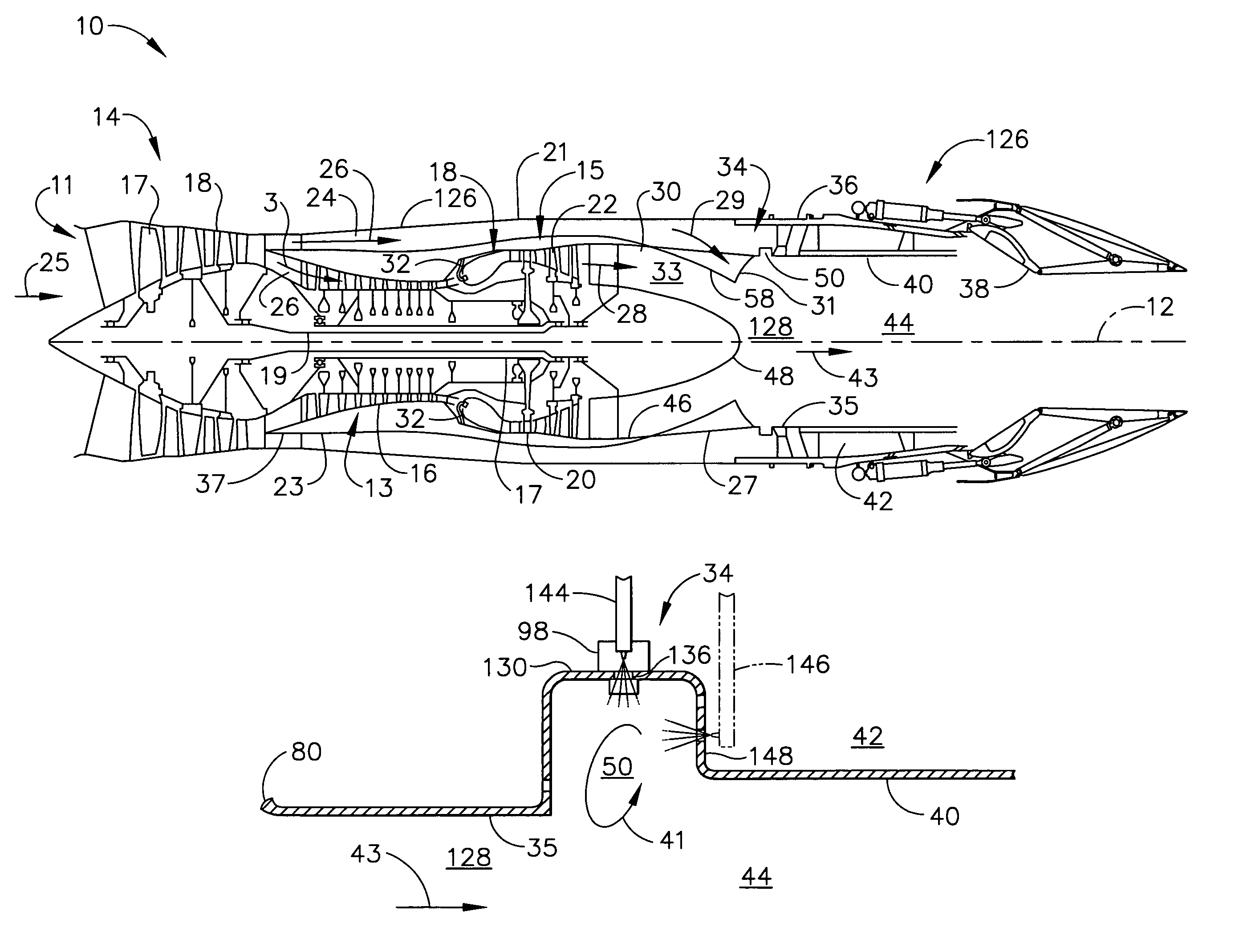
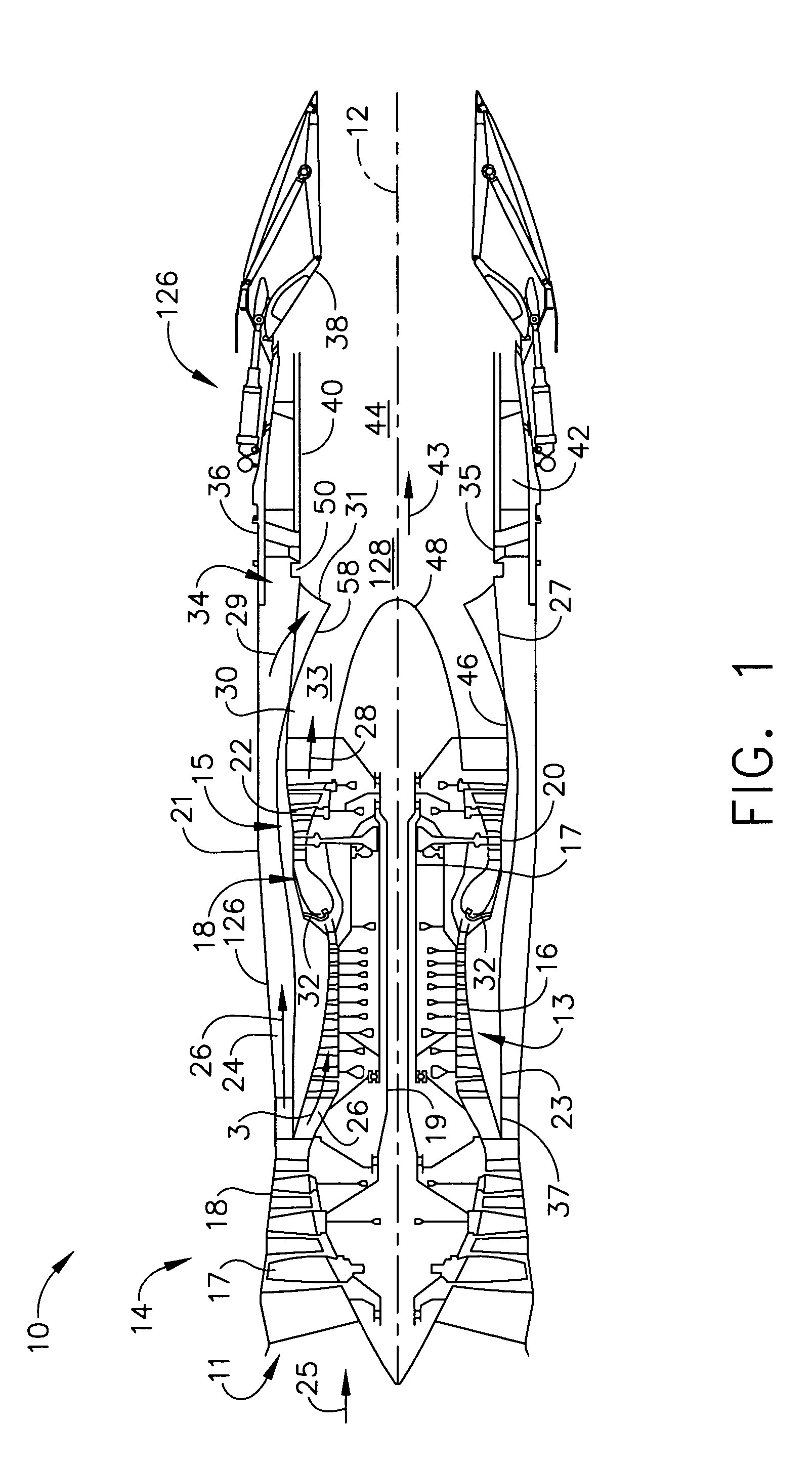
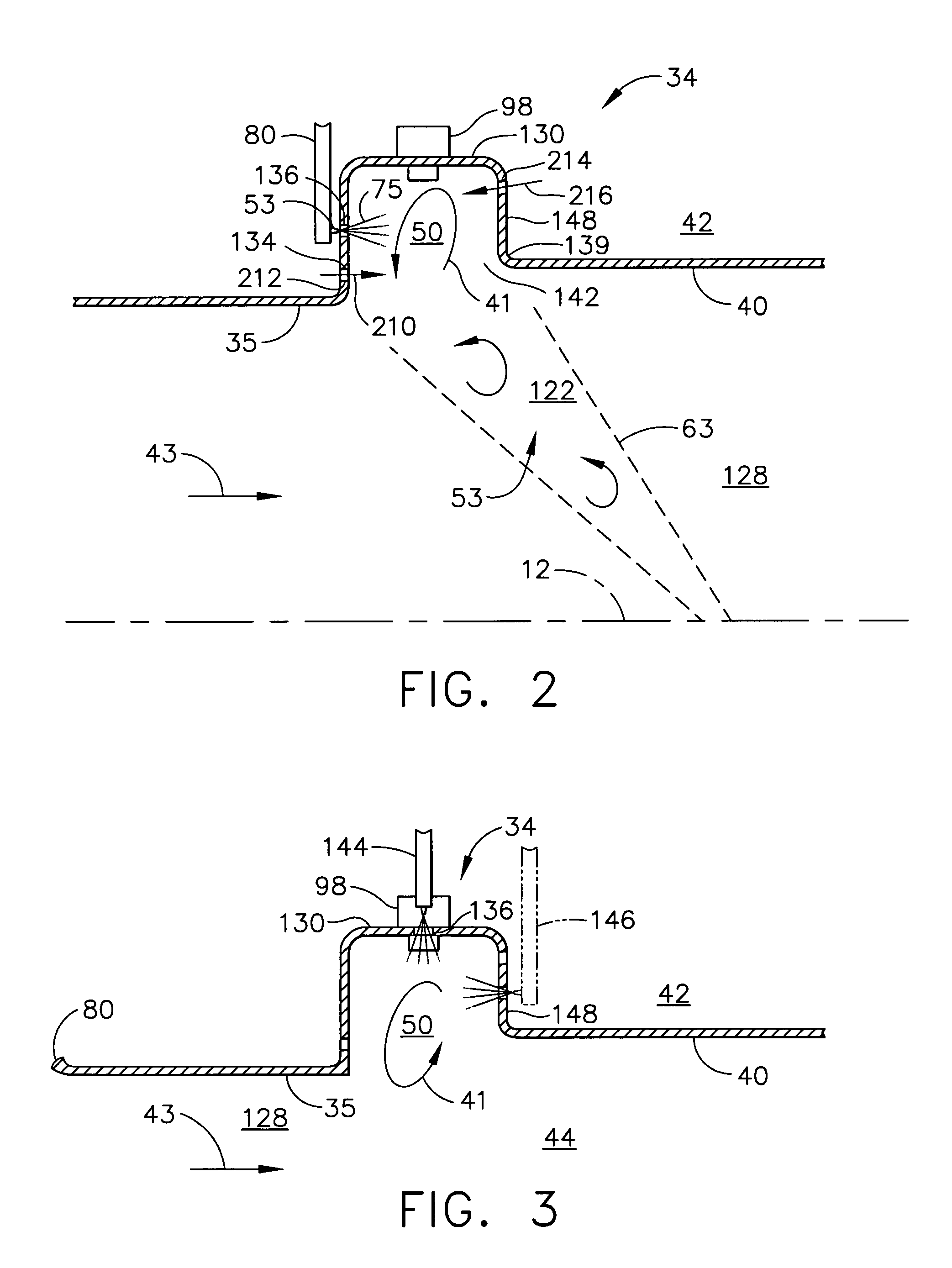
[0017]Illustrated in FIG. 1 is an exemplary medium bypass ratio turbofan gas turbine engine 10 for powering an aircraft (not shown) in flight having only one afterburner which is a trapped vortex cavity afterburner 34 located in an exhaust section 126 of the engine. The engine 10 is axisymmetrical about a longitudinal or axial centerline axis 12 and has a fan section 14 upstream of a core engine 13. The core engine 13 includes, in serial downstream flow communication, a multistage axial high pressure compressor 16, an annular combustor 18, and a turbine section 15. The turbine section 15 illustrated herein includes a high pressure turbine 20 suitably joined to the high pressure compressor 16 by a high pressure drive shaft 17. Downstream of the turbine section 15 and the core engine 13 is a multistage low pressure turbine 22 suitably joined to the fan section 14 by a low pressure drive shaft 19. The core engine 13 is contained within a core engine casing 23 and an annular bypass duct...


PUM


Abstract

A trapped vortex cavity afterburner includes one or more trapped vortex cavity stages for injecting a fuel / air mixture into a combustion zone. The trapped vortex cavity afterburner is operable to provide all thrust augmenting fuel used for engine thrust augmentation. Each stage has at least one annular trapped vortex cavity. The trapped vortex cavity afterburner may be a multi-stage afterburner having two or more trapped vortex cavity stages ganged for simultaneous ignition or operable for sequential ignition. One embodiment of the annular trapped vortex cavity is operable to raise a temperature of an exhaust gas flow through the afterburner about 100 to 200 degrees Fahrenheit. Each of the trapped vortex cavity stages may be operable to produce a single or a different amount of temperature rise of the exhaust gas flow through the afterburner. A chevron shaped trapped vortex cavity and having zig-zag shaped leading and trailing edges may be used.

Description

BACKGROUND OF THE INVENTION[0001]The present invention relates generally to aircraft gas turbine engines with thrust augmenting afterburners and, more specifically, afterburners and trapped vortex cavities.[0002]High performance military aircraft typically include a turbofan gas turbine engine having an afterburner or augmentor for providing additional thrust when desired particularly for supersonic flight. The turbofan engine includes in downstream serial flow communication, a multistage fan, a multistage compressor, a combustor, a high pressure turbine powering the compressor, and a low pressure turbine powering the fan. A bypass duct surrounds and allows a portion of the fan air to bypass the multistage compressor, combustor, high pressure, and low pressure turbine.[0003]During operation, air is compressed in turn through the fan and compressor and mixed with fuel in the combustor and ignited for generating hot combustion gases which flow downstream through the turbine stages whi...

Claims


Application Information

Patent Timeline
Patent Type & Authority Patents(United States)
IPC IPC(8): F02K3/10F23R3/18
CPCF23R3/20
Inventor KOSHOFFER, JOHN MICHAEL
Owner GENERAL ELECTRIC CO
Why Eureka
Try Eureka