Five valve manifold with angle bonnet details

a technology of manifolds and manifolds, applied in the field of five manifolds, can solve problems such as the difficulty of turning the handles by hand

Active Publication Date: 2007-06-05
PARKER HANNIFIN CANADA
View PDF10 Cites 10 Cited by
  • Summary
  • Abstract
  • Description
  • Claims
  • Application Information

AI Technical Summary

Benefits of technology

[0007]The general type of manifold is used in flow measurement applications in a variety of industries, including oil and gas, petrochemical, water treatment and power production. The manifold valve is installed between the primary flow measurement element (an orifice plate or similar) and the transmitter. The purpose of the primary element is to cause a pressure drop in the pipeline. There is a relationship between the size of the pressure differential caused by the primary element and the fl...

Problems solved by technology

However, the conventional positioning of the valves on and normal to a front face of the prior art manifolds requires...

Method used


Image

  • Five valve manifold with angle bonnet details
  • Five valve manifold with angle bonnet details
  • Five valve manifold with angle bonnet details

Examples


Embodiment Construction

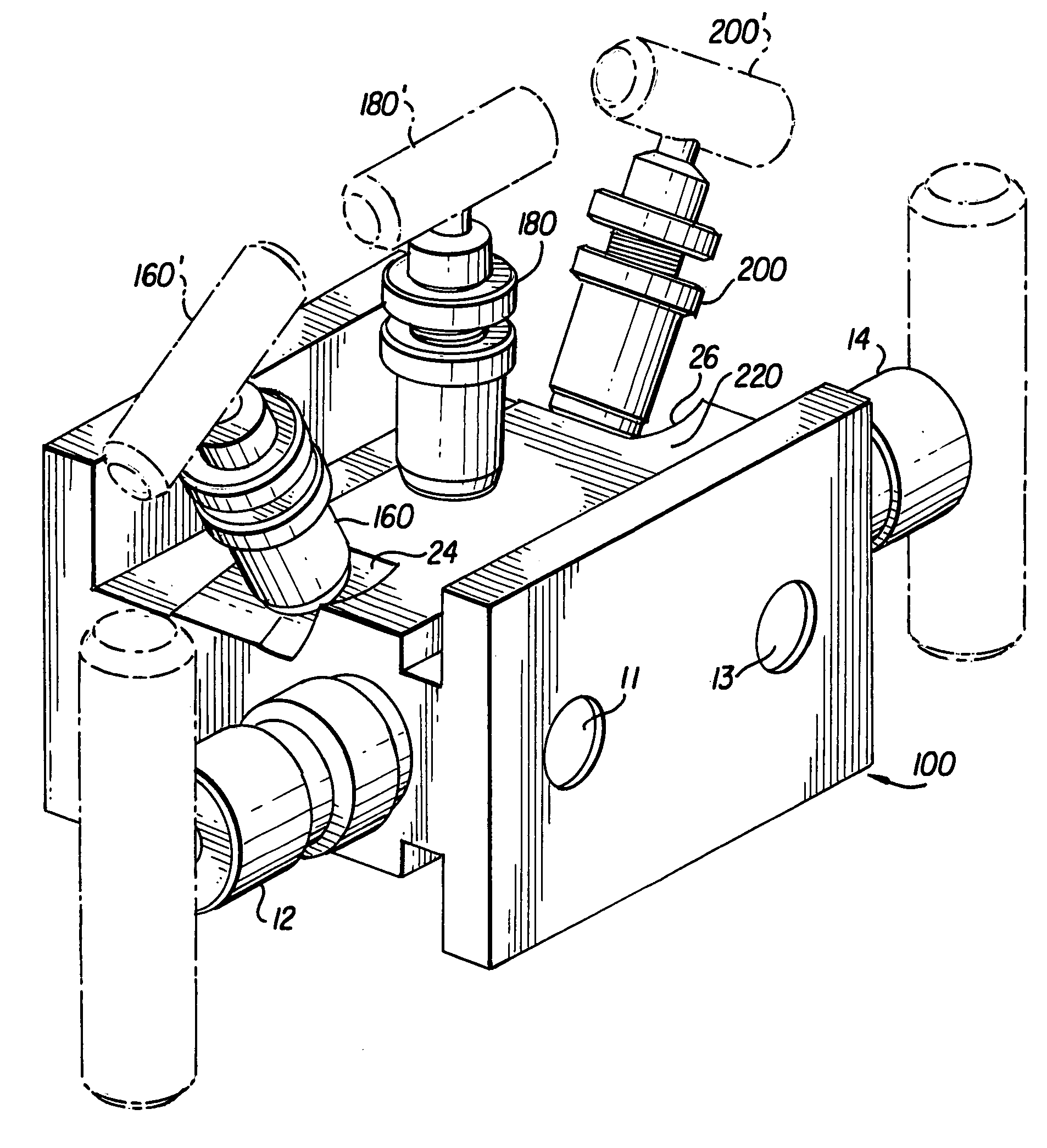
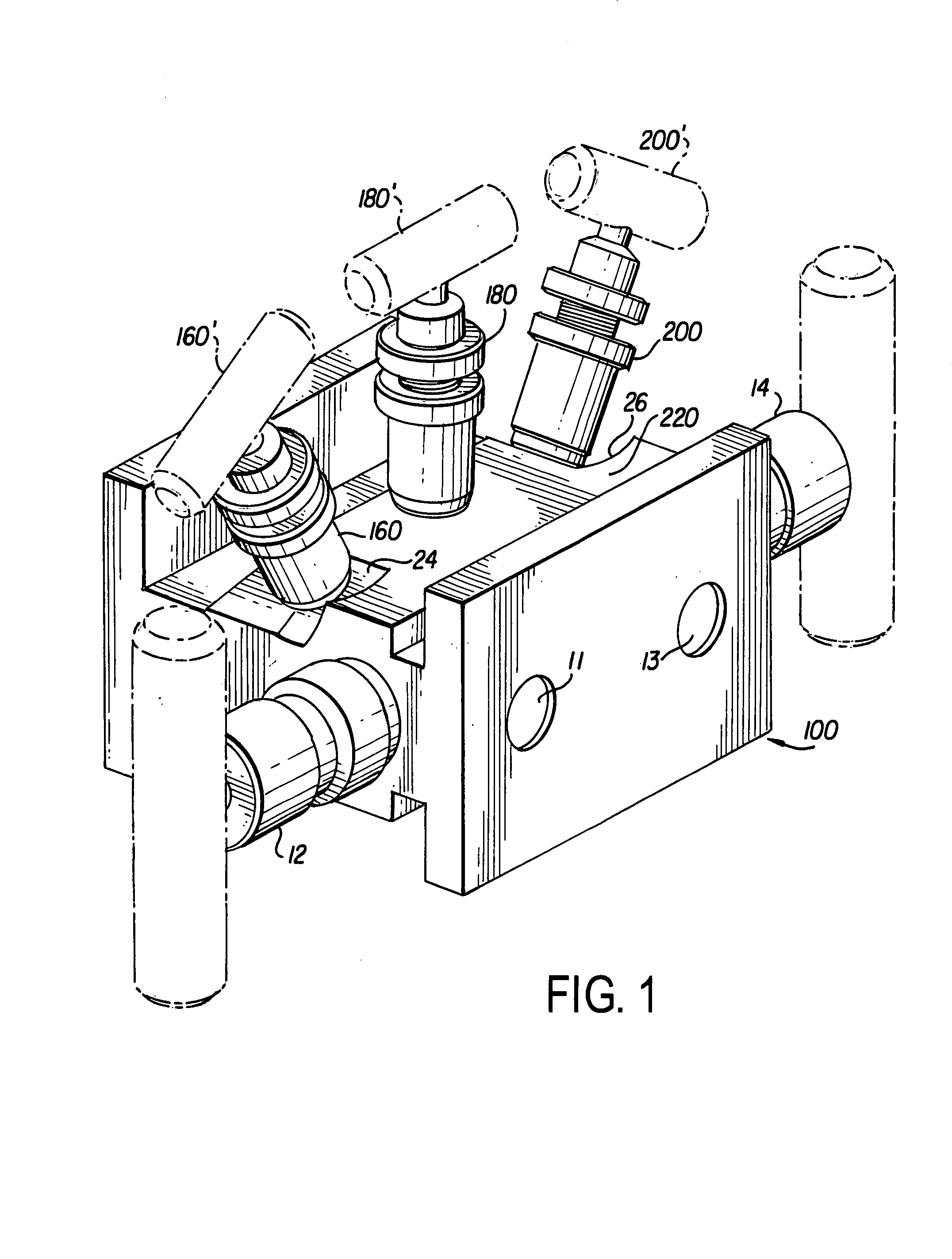
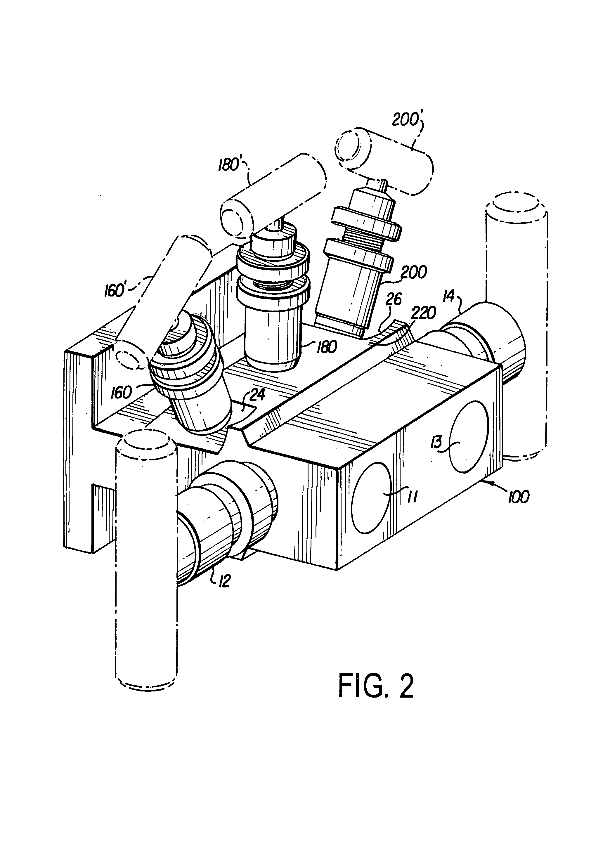
[0014]In such an installation as described above for flow measurement applications, there are two independent passages from the primary element through the manifold valve to the transmitter. One passage 11 is from the high pressure side of the primary element and the other passage 13 is from the low pressure side of the primary element. Two isolation or block valves (12, 14, respectively, one on each of the high side and low side) are located within the manifold to allow the transmitter (not shown) to be isolated from the pipeline. In all the drawings attached according to embodiments of the invention the isolation / block valves 12, 14 are located on the sides of the manifold.

[0015]The other three valves 16, 18, 20 in a five valve manifold are typically located on the front face 22 of the manifold body (see prior art drawings FIGS. 3–4). These valves 16, 18, 20 are either used as equalizer valves or vent valves. Five valve manifold can have either 2 equalizer valves and one vent valv...


PUM


Abstract

A multi-valve manifold is provided, including a valve body having a periphery about which are placed a series of valves. At least one of the series of valves fits within a depression in the valve body.

Description

BACKGROUND OF THE INVENTION[0001]1. Field of the Invention[0002]The invention relates to the field of five valve manifolds and the attached assembly drawings show the general arrangement of two types of five valve manifolds incorporating angle bonnet features according to the invention.[0003]2. Description of the Related Art[0004]Drawing FIGS. 3, 3a, 4 and 4a show the same type of five valve manifold valve with the conventional arrangement of the valve bonnets, wherein:[0005]FIGS. 3 and 3a show a five valve, flange by pipe manifold with the equalizer and vent valves located on the front face of the manifold.[0006]FIGS. 4 and 4a show a five valve, flange by flange manifold with the equalizer and vent valves located on the front face of the manifold.BRIEF SUMMARY OF THE INVENTION[0007]The general type of manifold is used in flow measurement applications in a variety of industries, including oil and gas, petrochemical, water treatment and power production. The manifold valve is install...

Claims


Application Information

Patent Timeline
IPC IPC(8): F16K11/20
CPCF16K27/003Y10T137/87249
Inventor STAMLER, EDWARD
Owner PARKER HANNIFIN CANADA
Why Eureka
Try Eureka