EGR system for an internal combustion engine

a technology of internal combustion engine and egr, which is applied in the direction of machines/engines, output power, mechanical equipment, etc., can solve the problems of slowing down the chemical reaction of the combustion process, reducing the formation of nitrous oxide (nox), and lowering the maximum combustion temperature within the cylinder

Inactive Publication Date: 2013-05-14
DEERE & CO
View PDF11 Cites 8 Cited by
  • Summary
  • Abstract
  • Description
  • Claims
  • Application Information

AI Technical Summary

Problems solved by technology

The exhaust gas which is reintroduced to the engine cylinder reduces the concentration of oxygen therein, which in turn lowers the maximum combustion temperature within the cylinder and slows the chemical reaction of the combustion process, decreasing the formation of nitrous oxides (NOx).
Furthermore, the exhaust gases typically contain unburned hydrocarbons which are burned on reintroduction into the engine cylinder, which further reduces the emission of exhaust gas by-products which would be emitted as undesirable pollutants from the IC engine.
The impact of the higher exhaust pressures significantly increases pumping losses, and raises peak firing pressures.
It is also difficult to drive EGR levels high enough to meet NOx regulations without aftertreatment.

Method used


Image

  • EGR system for an internal combustion engine
  • EGR system for an internal combustion engine

Examples


Embodiment Construction

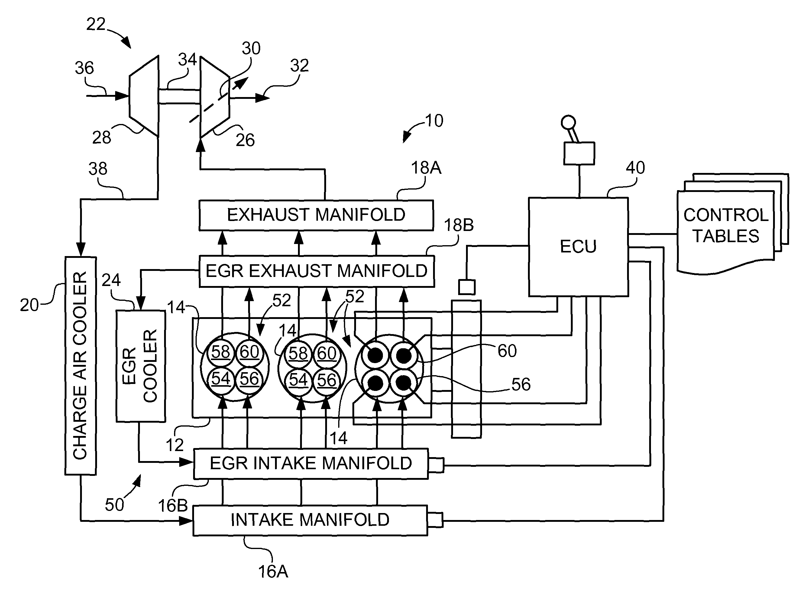
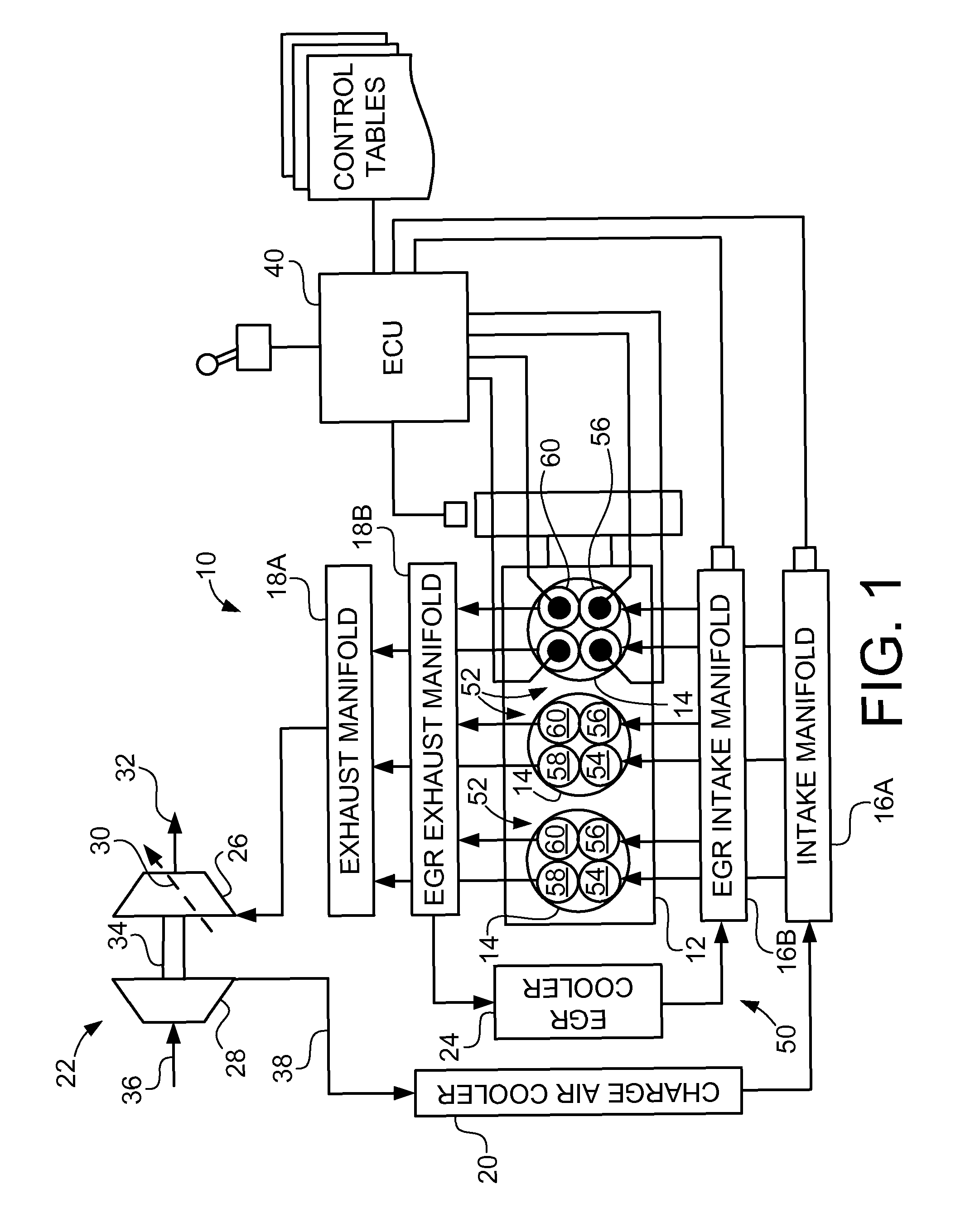
[0013]Referring now to FIG. 1, there is shown an embodiment of an IC engine 10 of the present invention, which generally includes a block 12 having a plurality of combustion cylinders 14, intake manifold 16A, EGR intake manifold 16B, exhaust manifold 18A, EGR exhaust manifold 18B, charge air cooler 20, turbocharger 22, and EGR cooler 24. In the embodiment shown, IC engine 10 is a diesel engine which is incorporated into a work machine, such as an agricultural tractor or combine, but may be differently configured, depending upon the application.

[0014]Block 12 is typically a cast metal block which is formed to define combustion cylinders 14. In the embodiment shown, block 12 includes three combustion cylinders 14, but may include a different number depending upon the application. Intake manifold 16A and exhaust manifold 18A are also typically formed from cast metal, and are coupled with block 12 in conventional manner, such as by using bolts and gaskets. Intake manifold 16A and exhaus...


PUM


Abstract

An EGR system for an IC engine, wherein the IC engine includes a block defining a plurality of combustion cylinders, a plurality of multi-valve heads, each multi-valve head associated with a respective combustion cylinder and including an inlet valve and an exhaust valve, an exhaust manifold fluid coupled with each exhaust valve, and an intake manifold fluidly coupled between the exhaust manifold and each inlet valve. The EGR system includes:a plurality of EGR inlet valves and a plurality of EGR exhaust valves, wherein each multi-valve head includes at least one EGR inlet valve and at least one EGR exhaust valve;an EGR exhaust manifold fluidly coupled with each EGR exhaust valve; andan EGR intake manifold fluidly coupled between the EGR exhaust manifold and each EGR inlet valve.

Description

FIELD OF THE INVENTION[0001]The present invention relates to internal combustion engines, and, more particularly, to exhaust gas recirculation systems in such engines.BACKGROUND OF THE INVENTION[0002]An internal combustion (IC) engine may include an exhaust gas recirculation (EGR) system for controlling the generation of undesirable pollutant gases and particulate matter in the operation of IC engines. EGR systems primarily recirculate the exhaust gas by-products into the intake air supply of the IC engine. The exhaust gas which is reintroduced to the engine cylinder reduces the concentration of oxygen therein, which in turn lowers the maximum combustion temperature within the cylinder and slows the chemical reaction of the combustion process, decreasing the formation of nitrous oxides (NOx). Furthermore, the exhaust gases typically contain unburned hydrocarbons which are burned on reintroduction into the engine cylinder, which further reduces the emission of exhaust gas by-products...

Claims


Application Information

Patent Timeline
Patent Type & Authority Patents(United States)
IPC IPC(8): F02M25/07F02B47/08F02B33/44
CPCF02M25/0749F02B29/04F02M25/0707F02M25/0726Y02T10/121F02D13/0257F02M26/05F02M26/22F02M26/43Y02T10/12
Inventor VUK, CARL T.
Owner DEERE & CO
Why Eureka
Try Eureka